|
1. Creating a shape
return=>page top
Table of contents: Basic shape,
Line, Polyline, Cubic curve
1.1 Basic shape
|
Operation
|
Description
|
|
create

|
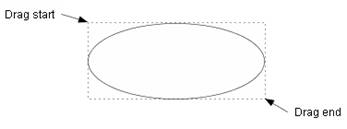
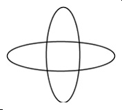
Click on the button representing the shape to be create and drag over the
canvas diagonally, then the basic shape which fits to the dragged rectangle
will be displayed (Figure_(a)).
 : :
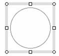
(1)To create a shape to fit a square, hold down the Shift or Ctrl
key while dragging with the mouse (Figure_(b)).
(2) If you click on the canvas, instead of draggng, then the small
shape will be created. This operation is a kind of a error processing,
so undesirable.
 |
 |
| (a)Create an ellipse |
(b)Create a circle with Alt key |
|
|
move, resize
|
Drag the selection box of the selected shape, then you can move the
selected shape.
Drag a resize handle of the selected shape, then you can change the size of the selected shape.
:
(1)Hold down the Shift or Ctrl key while dragging the shape, then the selected
shape will be moved horizontally or vertically.
(2) If a corner(NW/NE/SE/SW) resize handle is dragged with holding down
the Shift or Ctrl key, then the selected shape will be resized with keeping
its wide to height ratio (aspect ratio).
(3) If a corner(NW/NE/SE/SW) resize handle is dragged with holding down the Alt key,
then the selected shape will be forced to be a square.
(4) If the selected shape happens to be aligned with a neighboring shape
while being moved or resized, a red dashed line will displayed between
the two shapes. And if the mouse button is released at this moment, then
the selected shape will be aligned with the neighboring shape exactly within
round-off error.
 =>auto_align =>auto_align
 Resizing(Top of this page) Resizing(Top of this page)
|
|
add or delete text box
|
For a basic shape, a text box will be added to the shape when the shape
is created. If a text box is unnecessary, you can remove it using "delete
text box" command.
You can also execute "add/delete text box" command
selecting from the popup menu (popup menu).
=>Text box
|
|
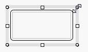
modify round rectangle
|
You can change the rounded corner radius of the selected round rectangle.
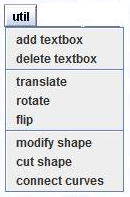
Click on the "util" button and select "modify shape"
menu, and then the following dialog will appear. And at the same time,
the control points (blue marks) will be displayed on the border of the
selected round rectangle (Figure_(a)).
You can do the same operation using popup menu.
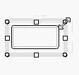
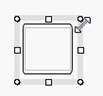
To change the radius of the rounded corners, drag the control point along
the edge(Figure_(b), (c)).
 |
| (a)Original round rectangle |
(b)Enlarge the radius |
(c)The maximum radius |
=>modify polyline, modify piecewise cubic curve, Ensuring connections for various operations
|
1.2 Line
return=>page top
|
Operation
|
Description
|
|
create

|
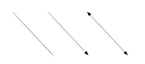
Click on the button on the toolbar and drag with the mouse on the
canvas(the drawing panel), then a straight line will be created. You can choose a line from the three types which are line, arrow and double
arrow.
:
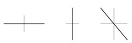
(1) Hold down the Shift or Ctrl key while dragging with the mouse, then
you can create a horizontal line, 45/135 degree line or vertical line which
is close to the dragging direction.
(2) If you click on the canvas instead of dragging, then the small diagonal
line will be created. This operation is a kind of a error processing, so
undesirable.
|
|
set arrow style

|
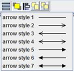
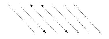
Click on the arrow style button and select a line style from the menu items,
then you can change the arrow style of the selected lines.
|
|
move an endpoint
|
Select a line, then the resize handles (endpoint marks) will be displayed
at the both ends of the line (Endpoint of a line).
Drag the endpoint with the crosshair cursor, then you can freely move the
endpoint of the line.
:
Hold down the Shift or Ctrl key while moving the endpoint, then the selected
line changed to a horizontal or vertical line.
|
|
move
|
Select a line, put the mouse on the line except its endpoints, and
drag the line with the move cursor, then the selected line will be moved
in parallel without changing its direction and length.
:
(1) Hold down the Shift or Ctrl key while dragging the line, then the selected
line will be moved horizontally or vertically.
(2) If the selected shape happens to be aligned with a neighboring shape
while being moved or resized, a red dashed line will displayed between
the two shapes. And if the mouse button is released at this moment, then
the selected shape will be aligned with the neighboring shape exactly within
round-off error.
=>auto_align
|
|
connector
|
A straight line and polyline can be used for a connector
which connects two shape objects.
=> Connector
|
1.3 Polyline (Polygonal line)
return=>page top
|
Operation
|
Description
|
|
create

|
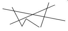
Click on the polyline button on the toolbar and click on the canvas (drawing
panel) to give the start point of a polyline. Then, move the mouse on the
canvas and you will see the line which connects the start point
and the current mouse position. If the current mouse position is appropriate
for your desired polyline, click the mouse button. That gives
the second point of the polyline. Repeat this operation, you can create
the point sequence of the polyline. To finish creating the polyline, click
the right button of the mouse or double-click, then you'll
get the last point of the polyline.
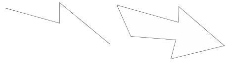
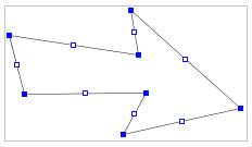
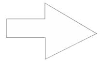
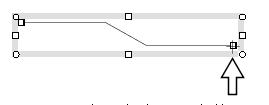
: Hold down the Shift or Ctrl key while moving the mouse, then the line
between the previous point and the current mouse position will be restricted
to a horizontal, 45/135 degree or vertical line. The following figure shows
a arrow shape which was created with holding down Shift key from the beginning
to the end.
|
|
set arrow style
|
Same operation for a line.
|
|
move an endpoint
|
If a polyline is not closed, then its endpoint of the polyline can be moved.
Select a polyline, then the resize handles (endpoint marks) will be
displayed at the both ends of the line (
Endpoint of a line segment).
You can move the endpoint by dragging with the crosshair cursor.
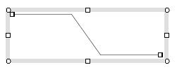
An original polyline |
Moves the end point rightward
with the crosshair cursor |
Moves the end point leftward
with the crosshair cursor |
Moves the end point upward
with the crosshair cursor |
:
Hold down the Shift or Ctrl key while moving the endpoint, then the endpoint
is moved horizontally or vertically.
|
|
move, resize
|
Moving shapes
Drag a selection box of a selected polyline, then the selected polyline
will be moved in parallel.
: Hold down the Shift or Ctrl key while dragging the polyline, then the
selected polyline, will be moved horizontally or vertically.
Resizing shapes
Drag the resize handle of a selected polyline, then the size of the selected
polyline will be changed as Figure_(b) and (c).
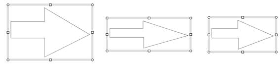 |
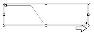
| (a) Original shape |
(b) Move N resize handle |
(c) Move NE resize handle |
:
(1) If a corner(NW/NE/SE/SW) resize handle is dragged with holding down
the Shift or Ctrl key, then the selected polyline will be resized with
keeping its wide to height ratio (aspect ratio).
(2) If a corner(NW/NE/SE/SW) resize handle is dragged with holding down
the Alt key, then the selected polyline will be forced to be a square.
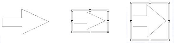 |
| (a) Original shape |
(b) Shfi/Ctrl key |
(c) Alt key |
:
If the selected shape happens to be aligned with a neighboring shape while
being moved or resized, a red dashed line will displayed between the two
shapes. And if the mouse button is released at this moment, then the selected
shape will be aligned with the neighboring shape exactly within round-off
error.
=>
auto_align
|
|
add or delete text box
|
For a basic shape, a text box will be added to the shape when the shape
is created. For a closed polyline (polygon), you can add a text box using
"add text box" command. You can also execute "add/delete
text box" command selecting from the popup menu (popup menu).
=>Text box
|
|
modify polyline
=>
modify other operations
|
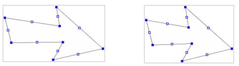
For the selected polyline, you can move a junction point (segment junction point) or
edge (straight line segment), add a new junction point to the polyline
or delete a existing junction point from the polyline.
Click on the "util" button and select "modify shape",
then the dialog below will appear.
At the same time, the control points (blue marks) will be displayed on the boundary of the selected polyline (Figure_(a)).
In the Figure_(a), a control point filled with blue is used for moving a junction point
and a control point located at a middle of an edge and filled with white is used for moving an edge.
At the initial state of the dialog, "move" button is selected.
If you change the state of the dialog, select the "add point"
or "delete point" button.
Figure_(a)
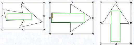
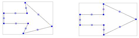
:
if you hold down the Shift or Ctrl key while dragging a junction point
(node poin), you can restrict the movement of the control point to horizontal
or vertical direction. And the same operation while dragging a middle point
of the edge makes the direction of the edge horizontal or vertical forcibly.
Using this rule, you can modify the shape easily as follows.
 |
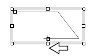
| (a)Original shape |
(b)Move the left edge to rightward |
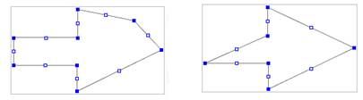
 |
| (c) Move edges with Shift key |
(d)Final shape |
If you want to add a junction point (segment junction point )to the selected polyline,
select "add point" button in the dialog and then click on an
edge of the polyline. Then a new junction point will be created at the
clicked point. You can move the new junction point, after selecting "move"
button in the dialog (Figure (e)).
To delete a junction point, select "delete point" button in the
dialog and then click on the junction point to be deleted (Figure (f)).
 |
| (e)Add a new junction point and move it |
(f)Delete a junction point |
Creating and modifying shapes(Top of this page)
=> modify other operations
=> Ensuring connections for various operations
|
|
connector
|
A polyline can be used for a connector which connects two shape objects.
=>Connector
|
1.4 Piecewise cubic curve
return=>page top
|
Operation
|
Description
|
|
create

|
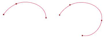
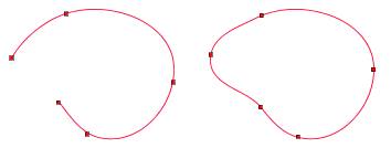
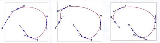
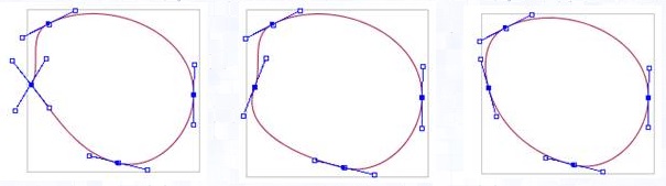
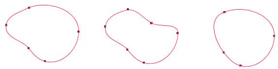
The procedure of creating a piecewise cubic curve is similar to that of creating a polyline. The clicked points are connected by multiple cubic
curves using a natural spline algorithm.The following figures show the process of creating a closed curve. The dots on the curve show the junction
points and a curve segment between two junction points is represented by 3-degree Bezier curve.
=>create polyline
|
|
set arrow style
|
Arrow style can't be set to a cubic curve.
|
|
move, resize
|
Moving shapes
Drag the selection box of the the selected cubic curve, then the selected cubic curve
will be moved in parallel.
: Hold down the Shift or Ctrl key while dragging the polyline, then the
selected the polyline, will be moved horizontally or vertically.
Resizing shapes
Drag the resize handle of the selected cubic curve, then the size of it
will be changed (Figure_(b), (c)).
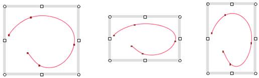 |
| (a)original shape |
(b)Move north resize handle |
(c)Move north-east resize handle |
:
(1) If a corner(NW/NE/SE/SW) resize handle is dragged with holding down the Shift or Ctrl key, then the selected shape will be resized with keeping its wide to height ratio (aspect ratio).
(2) If a corner(NW/NE/SE/SW) resize handle is dragged with holding down the Alt key, then the selected shape will be forced to be a square.
: If the selected shape happens to be aligned with a neighboring shape
while being moved or resized, a red dashed line will displayed between
the two shapes. And if the mouse button is released at this moment, then
the selected shape will be aligned with the neighboring shape exactly within
round-off error.
=>auto_align
|
|
add or delete text box
|
For a basic shape, a text box will be added to the shape when the shape
is created. For a closed piecewise cubic curves, you can add a text box
using "add text box" command. You can also execute "add/delete
text box" command selecting from the popup menu
(popup menu).
=>
Text box
|
|
modify piecewise cubic curve

=>
modify other operations
|
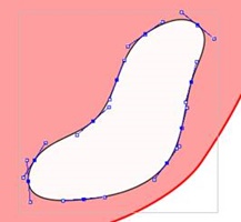
For the selected cubic curve, you can move a junction point (segment junction point) or
tangent line of the curve. You can also add a new junction point to the curve or
delete a junction point from the curve.
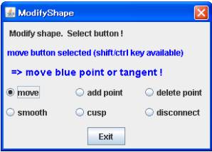
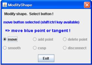
Click on the "util" button and select "modify shape"
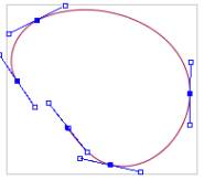
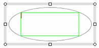
menu item, then the following dialog will appear. At the same time, the
control points (blue marks) and the tangent lines will be displayed on
the boundary of the selected curve (Figure_(a)). Here, control points filled
with blue are used to move the junction points, and the tangent lines are
used for changing the tangent directions at the junction points.
At the initial state of the dialog, "move" button is selected.
If you want to change it, click on the "add point" or "delete
point" button.
Figure_(a)
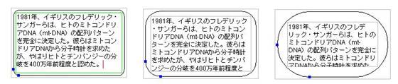
Click on the move button and drag a move a junction point (segment junction point)
or a tangent line with the mouse, then you can get a desirable curve.
Figure_(b): original curve
Figure_(c): move the second junction point to upper left.
Figure (d): move the tangent direction at the second node.
Figure (e): move the last node toward the first node to make the curve closed.
Figure (f): move the tangent direction at the first and the last node to remove the cusp point.
Figure (g): move the tangent direction at the first and the last node to make the curve smooth.
 |
| Figure_(b) |
Figure_(c) |
Figure (d) |
 |
| Figure (e) |
Figure (f) |
Figure (g) |
If you want to add a new junction point, select "add point" button in the dialog and click on a point on the curve, then a new junction point will be created at the clicked point. You can move the new junction point, after selecting "move" button in the dialog (Figure (i)).
To delete a junction point, select "delete point" button in the
dialog and click on the junction point to be deleted (Figure (j)).
 |
| (h) Original |
(i) Add point and move it. |
(j) Delete point |
Creating and modifying shapes(Top of this page)
:
The tangent lines often overlap each other at a small part of a shape
and may not easy to change their direction, then zoom up the shape.
The lengths of the tangent lines are constant regardless of the display magnification.
 |
|
 |
| Modifying a small part |
|
Zoom up |
=>
modify other operations
=>
Ensuring connections for various operations
|
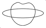
2. Auxiliary shape  return=>page top
|
Operation
|
Description
|
|
aux
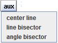
|
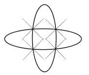
These commands are used for creating auxiliary lines such as center lines
and bisection lines.
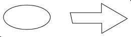
: The auxiliary lines are created with the property that disallows to change
the line direction by resizing operations. The property will be shown when
auxiliary lines are selected as follows.
=>Selecting shape, Shape format dialog
|
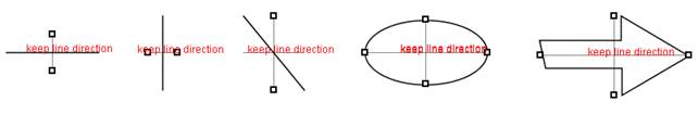
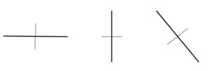
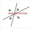
| center line |
Create the center lines for the selected shapes.
| The selected shapes |
The created center lines |
 |
 |
 |
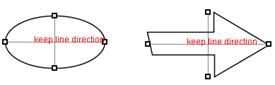 |
: The annotations of "keep line direction" imply that the
direction of the lines can't be changed by moving or resizing operations.
=>Selecting shape, Shape format dialog
|
|
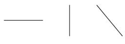
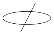
line bisector
|
The command is applicable only to straght lines and create bisected lines
for the selected lines.
| The selected shapes |
The created bisected lines |
|
|
 |
|
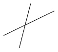
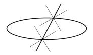
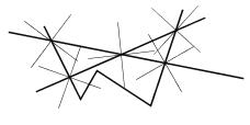
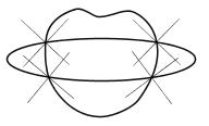
| angle bisector |
Create angle bisected lines between the intersected shapes which are selected.
| The selected shapes |
The created bisected lines of angles |
 |
 |
 |
 |
 |
 |
 |
 |
 |
 |
|
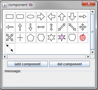
3. Component Library
return=>page top
|
Operation
|
Description
|
|
lib

|
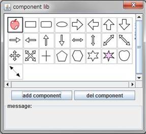
Click on the "lib" button, then the "Component lib"
dialog will open.
 |
Operation video: Component Library

|
|
add a component
to the dialog |
Selects shapes on the canvas (drawing panel) and press "add component"
button, then the selected shapes can be registered as library components.
If you selected multiple shapes, they will be registered as multiple components
at once. To register as one component, the multiple shapes must be grouped.
|
Delete a
component from
the dialog
|
Selects a component in the dialog and press "del component" button,
then the selected component will be deleted from the library. |
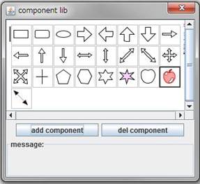
Change a
component
location |
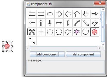
To change a component location on the dialog, first, press the mouse button
on the component to be moved, then the black thick border will be shown
around the component (Figure_(a)). Second, drag the component with the
mouse, then the thick black vertical line appears at the target position
(left-top in Figure_(a)). Third, release the mouse button, then the component
will be placed at the target position (Figure(b)).
 |
 |
| Figure_(a) Dragging a component to the left-top position |
Figure_(b) The component is placed at the left-top position |
| Changing a component location |
|
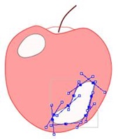
| Copy a component to the canvas |
Move a component to a desired location on the canvas by "Drag and
Drop" operation.
Create a new shape using the apple like component.
|
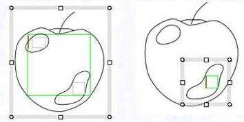
| Change shapes |
Selects shapes on the canvas (drawing panel), selects a component on the
dialog (star mark) , and press "change" button, then the selected
shapes change to the component shape (Figure_(b)).
The connection with connecters are ensured.
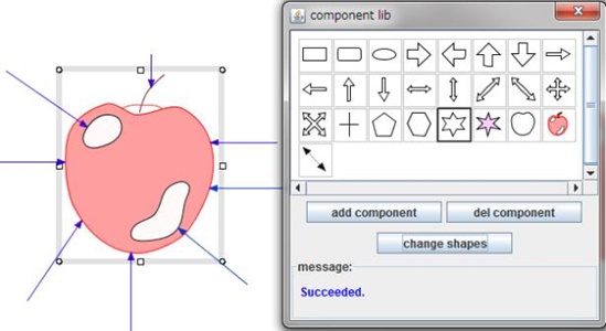
Figure_(a) Original (apple)
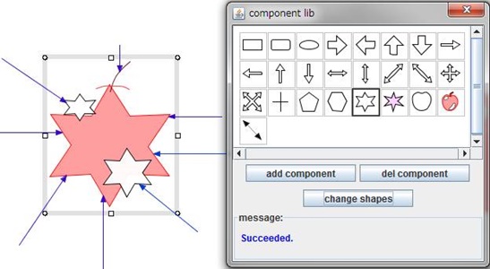
Figure_(b) Changes the selected shapes to star marks
=>Ensuring connections for various operations
|
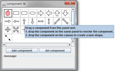
Multi-line tool tip
|
Because of a little complicated operation on the "Component lib"
panel, an "easy-to-understand, multi-lines" tool tip is used,.
The setting of the dismissal delay time for a tool tip is 60 seconds that
is much longer than the Java standard tool tip
 |
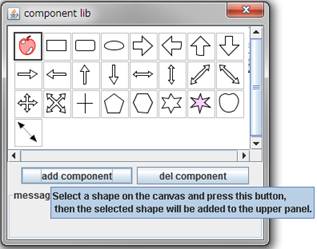 |
| Tool tips on the "Component lib" panel and "add component"
button. |
|
Copyright (c) 2009-2013
All other trademarks are property of their respective owners.
|
|
 Home
Home