|
Summary: First, this page describes the operations of auto align and connector.
Second, describes the operations of translating, rotating, fipping shape
objects and manipulating shape objects such as a shape object can be cut
by other shape and multiple curves can be connected via their intersection
points.
|
|
|
Table of contents:
auto align, connector,
translate, rotate,
flip, modify shape,
cut shape, connect curves
|
1. auto align
return=>page top
|
Operation
|
Description
|
|
auto align

|
Click on the "setting" button and then the following menu items
will appear.
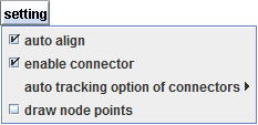
Select the "auto align" check box, then you can use the auto
align capability while moving or resizing shape objects. The default setting
of the check box is "selected".
The auto align capability automatically performs the same operation as
the align command in real time ,
while the selected shape is being moved or resized.
 =>align =>align
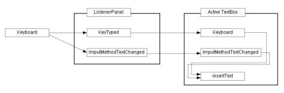
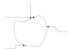
Figure_(a) is a block diagram which components are not aligned.
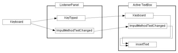
Figure_(a) Sample drawing: block diagram
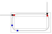
First we move the "Keyboard" box upward. If the "Keyboard"
box is aligned with a neighboring object within a given error margin, red
dashed lines are displayed as Figure_(b).
In Figure_(b), the "Keyboard" box and the "Keytyped"
box have the same size, therefore the three alignments of align_top, align_middle
and align_bottom are established at the same time and the three red dashed
lines appear.
If you release the mouse button at this moment, the "Keyboard"
box will be aligned with the "Keytyped" box accurately.
To confirm the align of the two boxes, press the mouse button on the selection
box of the "Keyboard" box, then the three red dashed horizontal
lines will appear again.
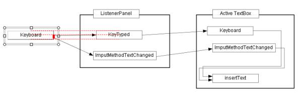
Figure_(b) Move the "Keyboard" box upward.
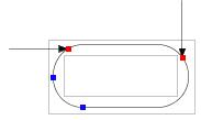
Next, moves the "Keytyped" box slightly to the left, then it
will aligned vertically with the "ListenerPanel" box and horizontally
with the "Keyboard" box and the red dashed lines will be displayed
horizontally and vertically as Figure_(c).
Release the mouse button at this moment, then "Keytyped" box
will be aligned with the "ListenerPanel" box and "Keyboard"
box simultaneously.
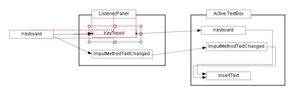
Figure_(c) Move the "Keytyped" box slightly to the left
Repeat moving and resizing operations, then finally we get Figure
(d).
Figure(d) The completion diagram.
More examples:
=>
Examples-1 Diagram, Table
|
|
auto align example1
- Separate shapes

|
The auto align capability automatically performs the same operation as the
align command
― align_left, align_center, align_right. align_top, align_middle, align_bottom
― in real time , while the selected shape is being moved or resized.
When you move or resize the selected shape and if the selected shape is aligned to other shapes,
then red dashed lines are displayed as sown in the the figures below.
When you release the mouse button while red dashed lines are being displayed,
the selected shape will be aligned with the other shapes very accurately.
 : API Specifications -
The shape being moved or resized is displayed with the Selection box. : API Specifications -
The shape being moved or resized is displayed with the Selection box.
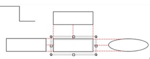
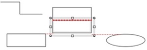
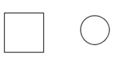
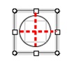
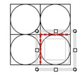
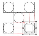
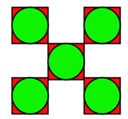
Figure 1.1-(1) Aligns the central rectangle to the neighboring three shapes
top-top, middle-middle, bottom-bottom , left-left, center-center, right-right
|
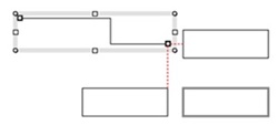
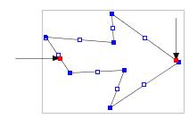
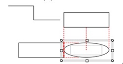
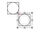
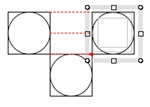
Figure 1.1-(2) Aligns the right end point of the polyline to the two rectangles
endp(endpoint)-middle,
endp(endpoint)-left
|
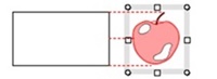
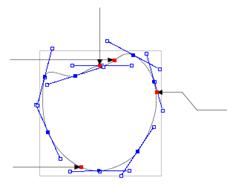
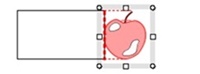
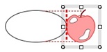
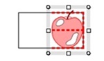
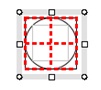
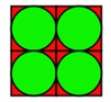
Figure 1.1-(3) Aligns the apple like shape(group) to the rectangle
top-top, middle-middle, bottom-bottom
|
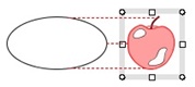
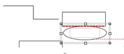
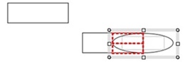
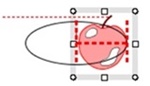
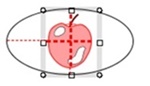
Figure 1.1-(4) Aligns the apple like shape(group) to the ellipse
top-top, middle-middle, bottom-bottom
|
Figure 1.1 Usual case - separate shapes
|
|
auto align example2 - Boundary overlap
|
|
|
auto align example3
- Overlap
|
|
|
auto align example4 - Align with Connectors
|
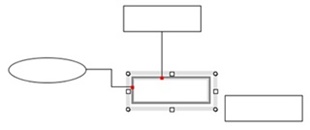
Figure 1.4-(1) Aligns shapes with connectors
|
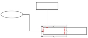
Figure 1.4-(2) Aligns the rectangle to the other one with the two connectors
|
Figure 1.4 Align with Connectors
: API Specifications:
The connections to connectors are assured by the special function
in the MoveResizeShapeLS.
|
|
auto align example5
-
Specific examples
|
|
2. Connectorreturn=>page top
creating a connector, Moving a connection point, Disconnecting, enable/disable connector, Auto tracking option, Moving a connector along guide lines, Connecting connectors to a group of shapes, Ensuring connections for various operations
|
Operation
|
Description
|
creating a connector
|
A straight line and polyline can be used for a connector which connects
two shapes.
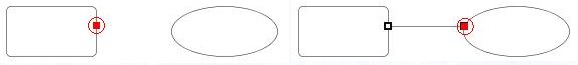
(1)Creating a connector -1
When you move the mouse toward a shape's boundary after pressing "creating
line or polyline button( ), you can see a connection mark as the figures (a), (a') below. ), you can see a connection mark as the figures (a), (a') below.
Press the mouse button to give the start point of a line or polyline
and drag the mouse toward another shape's boundary, then you can see a
connection mark on the another shape's boundary as the figures (b), (b').
Release the mouse button, then you give the end point of the line or polyline,
and finally you can get a connector of a line or polyline. To connect two
shapes with a horizontal or vertical line or polyline, you just drag the
mouse with holding down the Shift/Ctrl key.
=>Connection point
|
Figure_(a)Figure_(b)
|
|
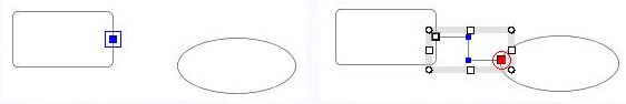
Figure (a')Figure (b')
|
(2)Creating a connector -2
If you already created a line or polyline, you can connect it to another
shape as a connector by moving the endpoint of the line or polyline.
Press the mouse button on the resize handle (endpoint mark)
of a selected line or polyline and drag it toward the another shape (Figure_(c), (c')),
you can see a connection mark on the another shape's boundary.
Release the mouse button, then you can connect the line or polyline
to the another shape.
To connect two shapes with a horizontal or vertical line or polyline, you
just drag the resize handle with holding down the Shift/Ctrl key.
=>
Cursor mark,
Move the endpoint of a line,
Move the endpoint of a polyline
Figure_(c)Figure (d)
|
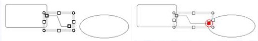
Figure (c')Figure (d')
|
:
A connector can be connected to an arbitrary point on a shape's boundary,
and the shape can be connected by any number of connectors
on its boundary.
|
|
Moving a connection point
|
If you want to move the connection point of a connector, move the connector's
endpoint along the shape boundary.
|
|
Disconnecting
|
If you want to disconnect a connector, move the connector's endpoint away from the shape boundary.
|
|
enable/disable connector
|
Select the "enable connector" check box, then the connector capability can be used.
The default setting of the check box is "selected".
Deselect the "enable connector" check box, then all the connector
will be handled as simple lines or polylines.

|
|
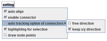
Auto tracking option
|
If the target shape is moved or resized, then the connector's endpoint moves
with the target shape to keep its connection.
The "auto tracking option" can constrains the directions of connectors
when the connectors tracks the target shape.
auto tracking option: free direction
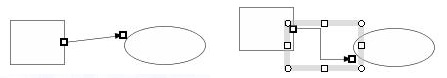
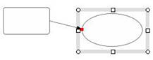
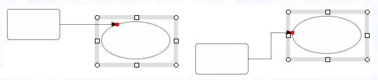
If the " free direction" option is selected, then a connector is moved or transformed as follow.
The Figure_(a) shows the original drawing and Figure_(b), (c) show the
scene when the ellipse is being moved upward and downward. The line
connector tracks the ellipse and keeps its connection with the
ellipse (the red marks represent the connection points). Here, the polyline
connector keeps its x directional feature ((d)-(f)), however the line connector
loses it completely.
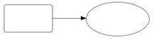
(a) Original |
|
| (b) The ellipse was moved upward/B> |
(c) The ellipse was moved downward |
|
Line connector
|
|
| (d) Original |
|
| (e) The ellipse was moved upward |
(f) The ellipse was moved downward |
Polyline connector
|
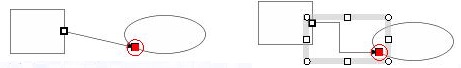
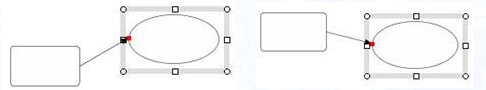
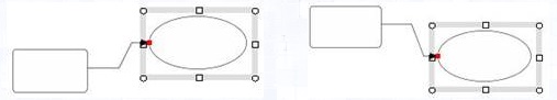
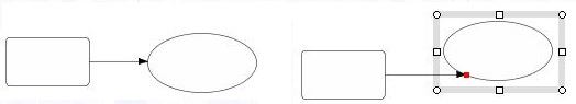
auto tracking option: keep x/y direction
If this option is selected, then the connector is moved or transformed
without losing its x/y directional feature. The Figure_(a) - (f) show the
scene of a line connector when the ellipse is being moved upward and downward.
The line connector doesn't lose its x directional feature and keeps the
connection with the target shape (the ellipse) by sliding the connection
point on the boundary of the target shape.
Here, the new connection point is calculated in real time as the intersection
point between the extended line of the connector and the target shape.
If the target shape (the ellipse) is moved largely, the line connector
changes to a polyline connector to keep the connection.
|
| (a) Original |
(b) The ellipse was moved upward |
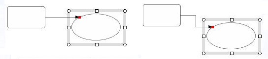
|
| (c) The ellipse was moved downward |
(d) The ellipse was moved downward largely, then the line connector
is changed to a polyline connector. |
|
|
(e) The ellipse was moved upward, then the polyline connector returns to a line connector.
|
(f) The ellipse upward largely, then the line connector is changed to a polyline connector again.
|
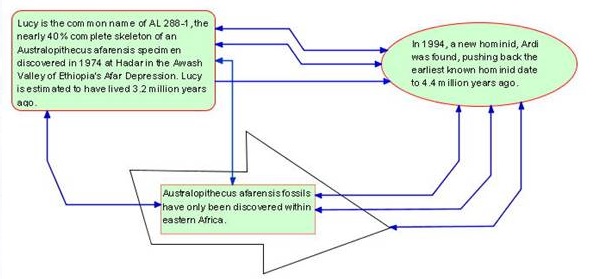
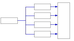
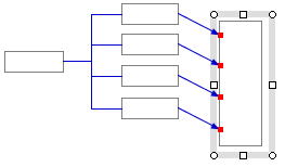
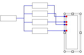
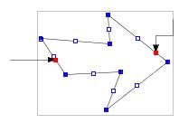
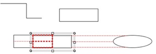
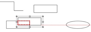
The following figures (a) - (c) are the typical and practical examples.
The "auto tracking option: keep x/y connectors" option provides a
very useful capability with the auto align function for drawing block diagrams, flow charts and so on. In the following
figures, the rectangles enclosed by the selection box are moved upward.
|
|
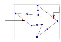
| (a)Original |
(b)option: free direction
If the right rectangle is moved downward, then the line connectors change their directions.
|
|
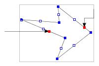
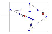
(c) option: keep x/y direction
If the right rectangle is moved downward largely,
then some of the line connectors change to polyline connectors.
|
=>Example 1.1
|
|
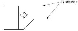
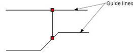
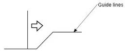
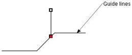
Moving a connector along guide lines.
|
A connector (a line or a polyline) can be moved along guide lines by dragging the mouse
with holding down Ctrl/Shift key.
If there is no guide line, the connector will be moved horizontally or
vertically with holding down Ctrl/Shift key.
This command is prepared to move a line in a table.
=>
Example 1.2.
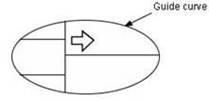
The guide line can be a curve and the connector can be a polyline.
|
|
|
|
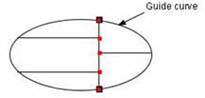
(a) Original
The vertical line connects to the guide curve.
|
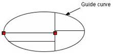
(b) Moves the vertical line rightward along the guide curve.
|
(c) Moves the horizontal line downward.
|
|
|
Connecting connectors to a shape of a group
|
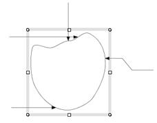
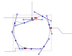
A connector can be connected to any shape of a group.
The apple-like object is a group which consists of the five piecewise cubic
curves and the arrow lines are connectors.
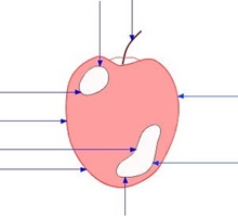
Figure_(a) Original
Figure_(b) shows the scene that the apple has been moved upward and downward
under the "keep x/y direction" option,
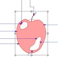
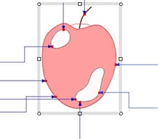
Figure_(b) Moving the "apple" upward and downward.
|
Ensuring connections for various operations
|
The connectors' connections is ensured for various operations.
∙ modify shape
=> modify polyline, modify piecewise cubic curve, modify round rectangle
 |
 |
 |
| Original - polyline |
Move the cusp point of the arrow leftward |
Move the cusp point leftward largely |
 |
 |
 |
| Delete the left lower junction point |
Add a new junction point |
Move the new junction point |
 |
 |
 |
| Original - piecewise cubic curve |
Move two junction points |
The same on the left figure |
 |
 |
|
| Move the bottom node upward |
The same on the left figure |
|
 |
 |
 |
| Original - round rectangle |
Move a blue point and change the radius |
Maximum radius |
∙ change shape
 |
 |
 |
| Original |
Change the round rectangles to ellipses |
Change those to the star marks |
 |
 |
 |
Original
(a group of piecewise cubic curves) |
Change each piecewise cubic curve to the hexagon. |
Change each shape to a the star mark. |
|
3. Translation and manipulation
return=>page top
Command: translate, rotate,
flip, modify shape,
cut shape, connect curves
|
Operation
|
Description
|
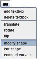
translate
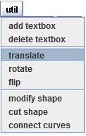
|
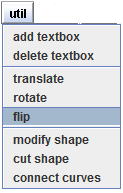
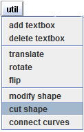
Select shapes, click on the "util" button and select the "translate"
menu item, then the dialog of the Figure_(a) appears. If no shape is selected,
then an error message is displayed at the top of the dialog(Figure(b)).
∙ Specify the (x,y) of the "translation x,y" in the spinners..
The unit of length for the (x,y) components can be selected by "pixel"
button or "mm" (millimeter) button.
If the "Click two points" check box is selected, then the (x,y)
components can be specified by the difference of two points.
You can click the two points on shapes (Figure_(c), (d)) or on empty place on the canvas.
∙ If the "Copy yes" button is selected, then the original shape remains after translated.
: You can click on the "Go" button repeatedly (Figure (e)).

Figure (e)
|
rotate
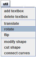
|
The rotating operation is similar to the translating operation.
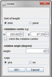
Select shapes, click on the "util" button and select the "rotate"
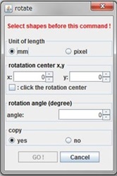
menu item, then the dialog of the Figure_(a) appears. If no shape is selected,
then an error message is displayed at the top of the dialog(Figure(b)).
:
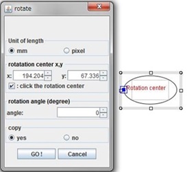
When the dialog appears, the "Rotation center" is also
displayed at the center position of the selected shapes as the figure below.
The "Rotation center" can be changed by using the x, y spinners,
or clicking on the canvas or a shape (Figure_(c), (d)).
|
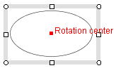
One selected shape
|
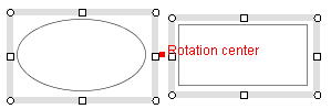 Two selected shapes
|
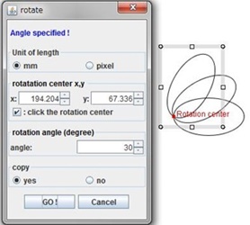
∙ If the "Copy yes" button is selected, then the original shape remains after rotated.
∙ The "Go" button can be clicked repeatedly.
: You can click on the "Go" button repeatedly (Figure (e)).
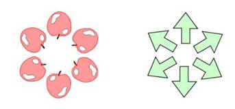
Figure (e)
|
flip
|
Select shapes, click on the "util" button and select the "flip"
menu item, then the dialog of the Figure_(a) appears. If no shape is selected,
then an error message is displayed at the top of the dialog(Figure(b)).
Select "Horizontally" or "Vertically" in the dialog,
select Copy yes/no button and click on the Go button, then the flipping
operation will be executed.
:
If you select Copy no button, the flipped shape will be placed at the
position slightly shifted from the original position for clarity (Figure (d)).
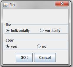
Figure_(a) |
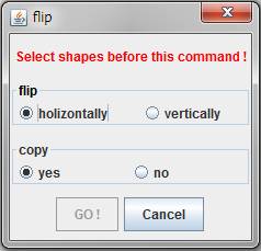
Figure_(b) |
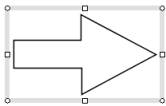
Figure_(c) Original shape |
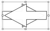
Figure (d) Result with Copy yes |
|
modify shape
|
Select the radio button representing the operation to be performed.
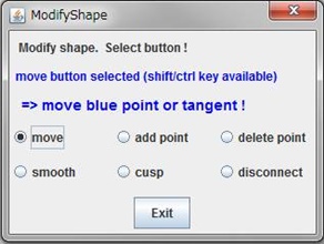
(1) move button
=>
modify round rectangle,
modify polyline,
modify piecewise cubic curve
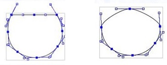
(2)add point button
Adds a junction point specified by mouse click to a curve.
|
| Original |
Adds the junction points on the upper and lower edges. |
(3)delete point button
Deletes a junction point specified by mouse click.
|
| Original |
Deletes the two junction points on the upper edge. |
(4)smooth button
Makes a curve smooth at the junction point specified by mouse click.
|
| Original |
Makes smooth at the start and end points of the upper edge. |
Moves the tangent directions. |
(5)cusp button
Makes a curve unsmooth slightly at the junction point specified by mouse click.
|
| Original |
Changes the bottom junction point to the cusp point. |
Moves the tangent at the cusp point. |
Ordinary display. |
(6)disconnect button
Disconnects a curve at the junction point specified by mouse click.
|
| Original |
Disconnect at the upper and lower junction points. |
Ordinary display. |
|
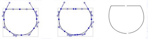
cut shape
|
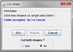
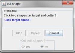
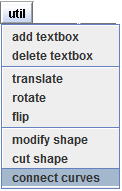
Click on the "util" button and select "cut shape" menu item,
then the dialog of Figure_(a) will be appears.
The operation is as follows.
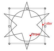
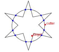
(1) Select two shapes.
The first shape is a target shape which is to be cut, and the second shape is a cutting shape (cutter).
After two shapes are selected, The "target" and
"cutter" string will be displayed on the canvas (Figure_(a)).
:
You can select the target shape before opening the dialog.
:
The "Go" button will be enabled after the cutter shape is selected.
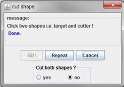
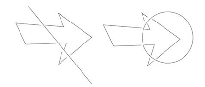
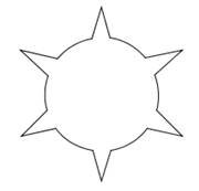
(2) Click on the "Go" button, then the cutting operation will
be executed with displaying the intersection points as the blue marks.
(Figure_(b), (c)).
:
If the "yes" button is selected in the dialog, the cutter shape will be also cut.
 |
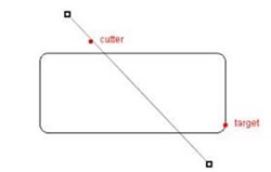 |
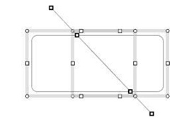
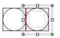
Figure_(a) Select a target shape and a cutting shape (cutter)
|
 |
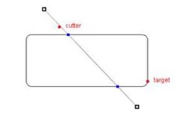 |
Figure_(b) the operation was executed by clicking "Go" button
|
 |
 |
Figure_(c) Display the selection boxes.
Click the Repeat button , then the dialog returns to the initial state.
|
Figure (d) shows the result of the case that two shapes have many intersection points.
 |
|
Figure (d)
|
|
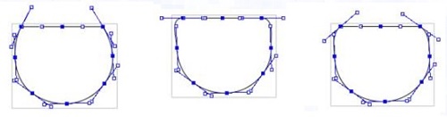
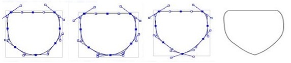
connect curves
|
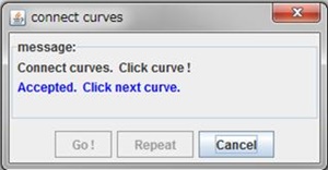
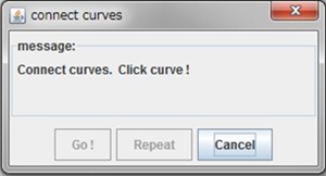
Click on the "util" button and select "connect curves"
menu item, then the dialog of Figure_(a) will open.
The operation is as follows.
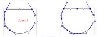
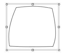
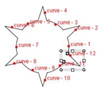
(1) Select multiple curves with the mouse click (Figure_(b)).
:
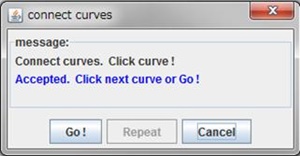
The "Go" button is enabled after at least two curves have been selected.
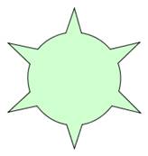
(2) Click on "Go" button, then a new connected curve will be displayed (Figure_(b), (c)).
:
The operation of connecting curves is executed according to the following rule.
⋅ If the n-th selected curve and (n+1)-th selected curve has a intersection point,
it will be junction point of the two selected curves. If they have no intersection,
then the junction point will be the closest pair of endpoints of the two curves.
⋅ If the n-th selected curve and (n+1)-th selected curve has multiple intersection points,
the operation of connecting curves will result in error.
In this case, you have to trim the n-th selected curve or (n+1)-th selected curve by using the
cut shape command before the operation.
 |
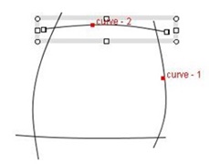 |
Figure_(a) Selecting curves
|
 |
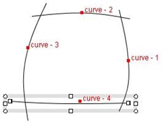 |
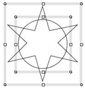
Figure_(b) All the curves are selected, then Click "Go"button.
|
 |
 |
Figure_(c) Connected curve
Click the Repeat button , then the dialog returns to the initial state.
|
|
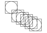
cut shape, connect curves example
|
 |
 |
 |
| (1) Original shapes |
(2) Cut each other:
Selecting target and cutter |
(3) Cut each other:
Result |
 |
 |
 |
| (4) Remove unnecessary parts |
(5) Connect curves:
Selecting curves |
(6) Connect curves:
Closed curve and filling color |
|
|
 Home
Home


 will be displayed. Click the mouse at the both end points, then the p1 and p2
(translation vector) will be determined. The (x,y) components of the translation
vector will be displayed in the x,y- spinners (x: 36, y: 28).
will be displayed. Click the mouse at the both end points, then the p1 and p2
(translation vector) will be determined. The (x,y) components of the translation
vector will be displayed in the x,y- spinners (x: 36, y: 28).