Command List
| Tab |
command |
| Home tab |
page, file, page, page layout, print, zoom |
| Shape tab |
page, zoom, undo,redo, edit, auto shape, aux(creating auxiliary shape), lib(library),
util (add text box , delete text box, translate, rotate, flip, modify shape, cut shape, connect curves),
setting, font, text align, color, line stroke, z-order of shapes, align, group, popupmenu |
| Help tab |
debug, test |
1. Home tabreturn=>page top
Command: page, file, page, page layout, print, zoom
|
Operation
|
Description
|
| page

|
These are the buttons frequent used in the page button.
∙ left arrow button: display previous page.
∙ right arrow button: display next page.
∙ + mark button: insert new page before or after the current page.
∙ x mark button: delete the current page.
|
zoom
 |
Click the zoom button, then the following dialog will appear.
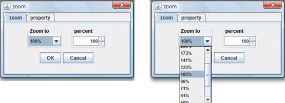
∙ Zoom to: Select a scale factor in the combo box.
∙ Percent: You can specify a scale factor in 1% increments.
Click the upward/downward arrow button, or specify the scale number
directly in the percent box.
 : Property tab isn't currently used. : Property tab isn't currently used.
|
|
file
|
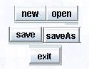
∙ new: open a new file.
∙ open: open an existing file.
∙ save: save a new file or existing file.
∙ saveAs: save a file with a new name.
∙ exit: quit or exit this application.
|
|
page
|
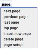
Click on the page button, then the following menu items appear.
∙ next page: display next page.
∙ previous page: display previous page.
∙ last page: display the last page.
∙ top page: display the top page.
∙ insert new page: insert new page before or after the current page.
∙ delete page: delete current page.
∙ page setup: set page size and page orientation.
|
page layout
 |
Click on the page layout button, then the dialog will opens and it shows
the page layout.
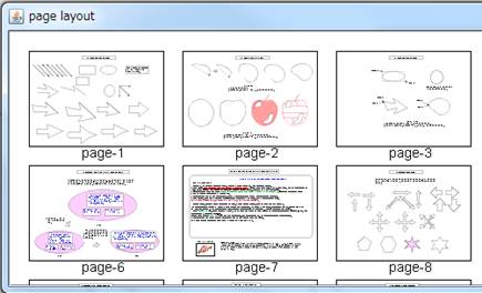
Figure_(a)
To move a page, press the mouse button on the page (press inside the black
frame) you want to move, and drag the page to the desired position, and
finally release the mouse button.
Here, when you press the mouse on the page, a black bold frame will be
displayed around the page as the Figure_(b) (e.g. page-3).And when you
drag the page, the black vertical line will appear at the target position
as the Figure_(b) (e.g. between page-1 and page-2).
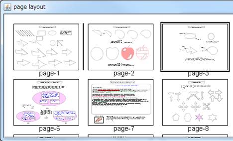
Figure_(b)
|
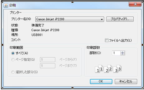
print
 |
Click on the print button, then the following dialog will appear.
|
2. Shape tabreturn=>page top
Command: page, zoom, undo,redo, edit, auto shape, aux(creating auxiliary shape), lib(library),
util (add text box , delete text box, translate, rotate, flip, modify shape, cut shape, connect curves),
setting, font, text align, color, line stroke, z-order of shapes, align, group, popupmenu
The shape tab is used for creating, manipulating a shape and so on.
|
Operation
|
Description
|
page
|
These buttons are the same as the buttons on the Home tab.
 =>page =>page
|
|
zoom
|
This button is the same as the button on the Home tab.
=>zoom
|
undo, redo
 |
You can undo and redo changes made to your drawing in the current session.
If there is no change in undo or redo, the button is displayed with gray.

|
| edit
delete

|
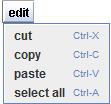
Click on the edit button, then the menu items will appear.
The menu items of cut, copy, paste and delete are used for editing shapes
and text in a text box.
The "select all" item is used for selecting all shapes on the
canvas(drawing panel).
=> Editing shape, Editing text
:
(1)You can use "Ctrl +x", "Ctrl +c" or "Ctrl +v"
key as an accelerator instead of selecting the menu items. An "Backspace"
key can be used for deleting shapes or text instead of "del"
menu item.
(2) If you click on the canvas before pasting shapes, the shapes in the
clipboard will be placed around the clicked point. If you don't click on
the canvas before pasting, the shapes will be placed on the lower right
of the original positions. If you continue paste, the shapes will be placed
on the lower right positions where the previous shape shapes are pasted.
|
auto_shape
|
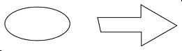
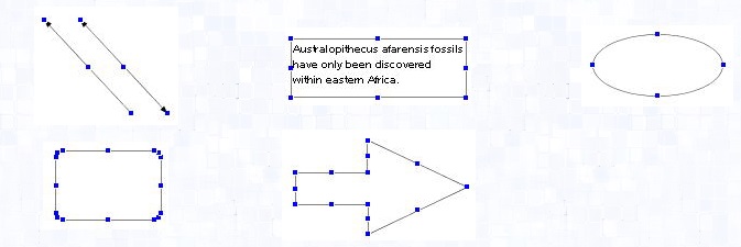
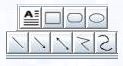
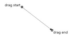
These buttons are used for creating a basic shape such as text box, rectangle,
round rectangle, ellipse/circle, line, arrow line, double arrow line, polyline
and cubic curve.
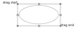
Click the corresponding button and drag with the mouse over the canvas(drawing
panel), the shape will appear on the canvas to fit the dragged area.
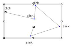
You have to specify junction points (segment junction points) to create a polyline
or a piecewise cubic curve, so you have to click on the canvas instead
of dragging with the mouse.
 |
 |
| Ellipse |
Straight line |
 |
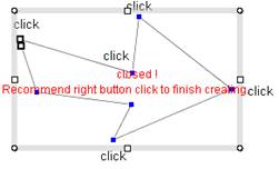 |
| Polyline |
Closed polyline |
=>Creating Shapes
 Creating and modifying shapes(Top of this page) Creating and modifying shapes(Top of this page)
|
aux
creating
auxiliary shape
 |
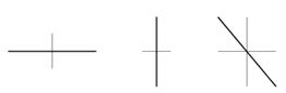
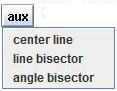
These commands are used for creating auxiliary shapes such as center lines
or bisection lines.
=>Auxiliary shape
∙ center line
Given lines/curves(bold) and the created center lines
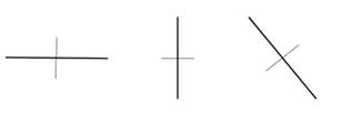
∙ line bisector
Given lines(bold) and the created bisected lines
∙ angle bisector
Create angle bisected lines between the intersected shapes which are selected.
Given lines/curves(bold) and the created bisected lines
|
|
lib

|
Click on the "lib" button, then the "Component lib"
dialog will open.
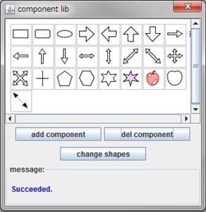
(1)Adds a component to the dialog panel :
Select shapes on the canvas(drawing panel) and press "add component"
button, then the selected shapes will be registered as library components.
(2) Deletes a component from the dialog panel:
Select a component on the dialog and press "delete component"
button..
(3) Changes a component location on the dialog panel (Reorder):
Move a component to the desiered location on the dialog panel by "Drag
and Drop" operation.
(4) Copies a component to the canvas:
Move a component to a desired location on the canvas by "Drag and
Drop" operation.
(5) Changes shapes to the component shape
Selects shapes on the canvas(drawing panel), selects a component on the
dialog, and press "change" button, then the selected shapes change
to the component shape.
=> Component Library
Component library (Top of this page)
|
|
util
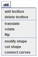
|
Select an operation by clicking util button.
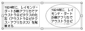
・add text box :
Select a closed shape on the drawing panel and press this button, then
a text box will be added to the selected shape. You can select multiple
shapes at once.
For a basic shape such as rectangle, round rectangle or ellipse, a text
box is added to the shape when the shape is created. However a text box
isn't added to a polygon (closed polyline) or a closed piecewise cubic
curve when the shape is created, because these type of shape will be almost
always modified or fine-tuned after its creation. So at the time you get
a satisfactory shape, you can add a text box using "add text box"
command.
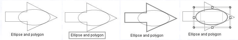
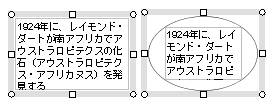
The calculation to define the appropriate text box area tries to find a
rectangle as large as possible which is inscribing to the shape boundary.
The calculation may be good for a convex shape, but not always satisfactory
for a concave shape (see the figure (c)). Therefore we provide the way
to change the text box area (move text box boundary).
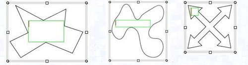
(a) (b) (c)
Figure_(c) shows that the rectangle at the arrow shape may be larger than
that at the center of the shape.
=>Text Box, move text box boundary
・delete text box
Delete a text box of a selected shape.
・translate
Translate selected shapes.
=> translate
・rotate
Rotate selected shapes. If the selected shapes have text boxes, then the
text boxes will be removed.
=> rotate
・flip
create mirror shapes for the selected shapes.
=> flip
・modify shape
This command changes the corner radius of a selected round rectangle, moves
the junction point (segment junction point) or the edge of a polyline, and moves the
junction point or tangent direction of a piecewise cubic curve.
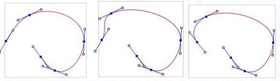
Modification of piecewise cubic curve
Moving junction points, changing tangent vector directions.
=> modify round rectangle, modify polyline, modify piecewise cubic curve
・cut shape
Cut a selected shape(target) by other shape(cutter).
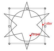
Cut each other:
Selecting target and cutter
|
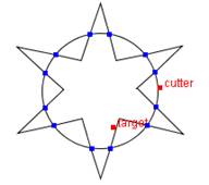
Cut each other: Result
|
=> cut shape
・connect curves
Connect multiple curves via their end points or intersection points.
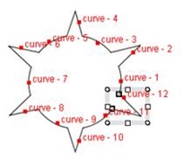
Connect curves:
Selecting curves
|
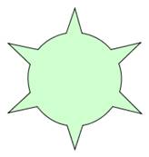
Connect curves :
Result and filling with color
|
=> connect curves
|
|
setting

|
Click on the "setting" button and then the following menu items
will appear.

∙ auto align: select the "auto align" checkbox, then the auto
align capability can be available while moving or resizing shape objects.
The default setting of the checkbox is "selected".
=>auto align
∙ enable connector: select the "enable connector" checkbox, then
the connector capability can be available while moving or resizing shape
objects. The default setting of the checkbox is "selected".
=> Connector
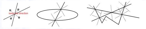
∙ auto tracking option of connectors
free direction/keep x/y direction
The "auto tracking option" can constrains the direction of a
connector when the connector tracks the target shape. If the checkbox of
"keep x/y direction" is selected, then x/y connectors will not
change their directions to track the target shapes.
=>Connector
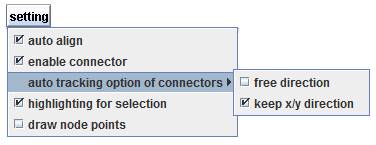
・highlighting for selection:
When the check box is on and if you move the mouse to a shape, the shape
starts highlighting.
The default state of the check box is "on". This function is
a support function of selecting shapes.
=>Selecting shapes、Highlighting a shape for selection
|
|
| Normal display |
Moving the mouse to the border of the text. |
Moving the mouse to the polygon. |
Moving the mouse to the ellipse and clicking the mouse button. |
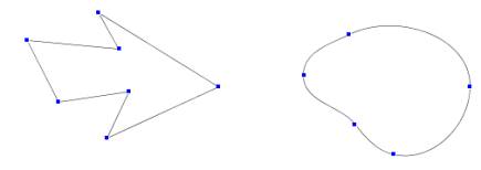
∙ Display junction points (segment junction points): select the "display node
points" checkbox, then the junction points of polylines and cubic
curves will be displayed as follows.
|
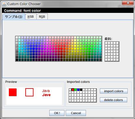
| font

|
Click on the font button, then the font menu dialog will open.
The text attribute of the selected text can be changed by using the combo
boxes or buttons in the dialog. Before changing the text attribute, the
text must be selected.
=>selecting text
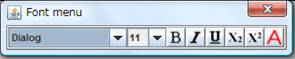
From the left in the dialog,
・Combo box of font family: select font family.
・Combo box of font size: select font size.
・B : Bold on/off.
・I : Italic on/off.
・U : Underline on/off.
・X2 : Subscript on/off.
・X2 : Superscript on/off.
・A : open the color chooser.
=>setting font style
|
| text align

|
Click on the text align button, then the pull down menu will appear. You
can change the text align of the selected text box.
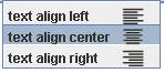
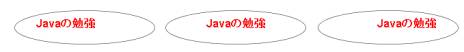
text align left text align center> text align right
:This menu is applicable for a group or multiple shapes.
|
| color

|
Set fill color or line color to selected shapes.
 : fill color, : fill color,  : line color : line color
Click on the button, then the following menu items will be displayed.
・no fill, no line: colorless or transparent.
・fill color, line color: display color chooser.
Before setting color, shape objects must be selected.
 
(a)The menus of fill color (b)The menus of line color
: This menu is applicable for a group or multiple shapes.
|
| line stroke

|
Set line width, line stroke or arrow style to selected shape objects.
Click on the button, then the following menu items will be displayed.
: Arrow style can be set to lines and polylines.
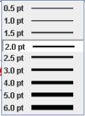 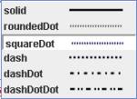 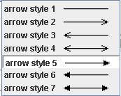
line width line stroke arrow style
: The menu item shown with white background is the line style of the selected
shape objects.
: This menu is applicable for a group or multiple shapes.
|
z-order of shapes

|
z-order of shapes determines the drawing order of shapes on the canvas(drawing
panel).
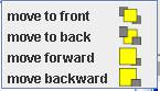
・move to front: Move selected shape(s) to top.
・move to back: Move selected shape(s) to bottom.
・move forward: Move selected shape(s) up one step.
・move backward: Move selected shape(s) down one step.
|
|
align

|
Click on the align button and then the following menu items will appear.
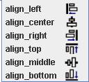
You can align the selected shapes vertically by the upper three menu items
and horizontally by the lower three menu items.
: see also auto align
|
|
group

|
 :group button, :group button,  :ungroup button :ungroup button
A set of shapes can be collected into a group. Once placed in a group,
the shapes can be manipulated together for moving, reseizing, copying,
coloring and so on. You can define a new group combining a group with other
shape(s) or group(s).
The grouping operations are as follows:
select two shapes grouping
|
| pop up menu |
Press the mouse right button on a shape's border , then the popup menu
will appear (Popup menu (a)). If the right button is pressed at empty space
, then the popup menu (b) will be displayed.
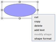
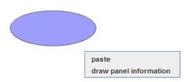
Popup menu (a) Popup menu (b)
・cut, copy, delete, paste=>Editing shape、Editing text
・add text=>add textbox
・modify shape=>modify shapes
・shape format=>Shape format dialog
・draw panel information=>Draw panel information dialog
|
3. Help tabreturn=>page top
Command:debug, test
|
Operation
|
Description
|
|
debug
|
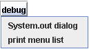
Click on the debug button and then the following menu items will be displayed.
・System.out dialog
Display the following dialog which displays the Java standard output and
error output.
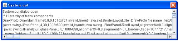
・print menu components
Output the menu components' list on the tool bar to the Java standard output.
Here the menu components are the buttons, pull down menus, combo boxes,
color choosers and so on which are registered to MenuUtil class by using
MenuUtil.setDrawMenu method.
|
|
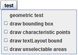
test
geometric test
|
Geometric test
"Geometric test" helps testing the stability of
the computing algorithm and the Newton-Raphson methods.
Click on "test" button and select "Geometric test"
menu, then the following dialog will open.
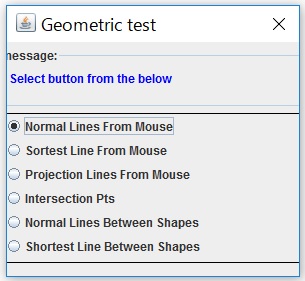
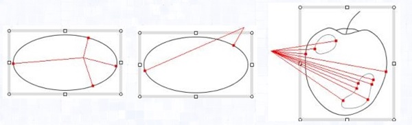
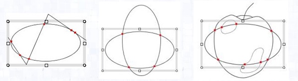
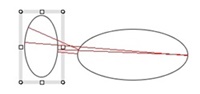
(1)Normal Lines From Mouse:
Select a shape and move the mouse on the canvas(drawing panel),
then the red lines will be displayed.
This function calculates the normal lines from the mouse pointer to the
selected shape object. It also displays the normal lines and their end points.
・API doc=>Geometric Library -
Normal lines to a curve from a point
・Unit Test Code=>Java Drawing Test Code -
Normal lines to a arbitrary curves
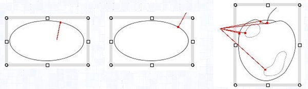
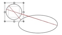
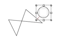
(2)Shortest Line From Mouse:
Select a shape and move the mouse on the canvas, then the red line
will be displayed from the mouse position to the selected shape.
This function calculates the minimum distance point from the mouse pointer
to the selected shape. It displays the minimum distance point as a red
mark and the red line from the mouse pointer to the minimum distance point.
・API Doc=>Geometric Library - Nearest point on a curve from a point
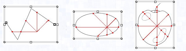
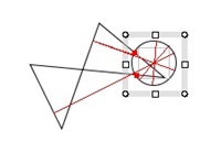
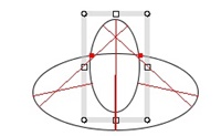
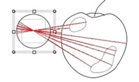
(3)Projection Lines From Mouse:
Select a shape and move the mouse on the canvas, then the red line
will be displayed from the mouse position to the selected shape like the
spokes of a wheel by 45° pitch.
This function calculates the projection points from the mouse pointer to the selected shape.
・API Doc=>Geometric Library -
projection points on the curve from a point with a projection vector
(4)Intersection Pts:
Select a shape and move it, then the intersection points between
the selected shape objects and the other shape objects will be displayed.
・API Doc=>Geometric Library -
Intersection points between two curves
・Unit Test Code=>Java Drawing Test Code -
Intersection between two arbitrary curves
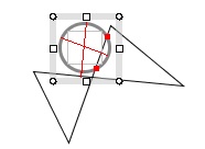
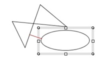
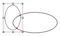
(5)Normal Lines Between Shapes:
Select a shape and move it to other shape, then the normal lines between
the two shapes will be displayed.
If the two shapes are crossing, the intersection points will be displayed as red marks.
・API Doc=>Geometric Library -
Common normal lines between two shapes
・Unit Test Code=>Java Drawing Test Code -
Common normal lines between two shapes
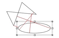
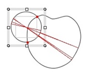
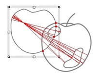
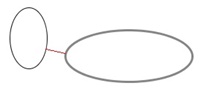
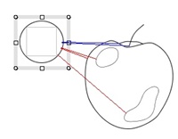
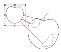
(6)Shortest Line Between Shapes:
Select a shape and move it to other shape, then the shortest lines between the two shapes will be displayed.
When the selected shape is a group shape, then the shortest line is displayed for each shape element.
And when the shortest line is a common normal line between shapes, then it is displayed as a red line,
and when it connects a endpoint or cusp point of the shapes, then it is displayed as a blue line.
If the two shapes are crossing, the intersection points will be displayed as red marks.
:
The processing speeds of the test (a), (b) and (c) are fast enough to
display the red lines in real time.The processing speed of test (d) is
not so fast compare with the test (a), (b) and (c), however simple drawing
like Figure (d) can be displayed in real time.
GeometricTest (Top of this page)
|
test
draw bounding box
|
This test shows the bounding boxes of shapes. The bounding box enclosing
a basic shape (rectangle, ellipse etc.) is always accurate, however, the
bounding box enclosing piecewise cubic curve isn't accurate and sometimes
required to be accurate for some kind of processing such as auto_align.
|
test
draw characteristic points
|
The characteristic points are endpoints of a line/curve segment, and north,
south, east and west points of an ellipse/circle.
Characteristic points
|
test
display textLayout bound
|
Show the rectangles which surround the java.awt.font.TextLayout objects
in a text box( Figure(b) ).
Figure_(a) Figure_(b)
|
4. Display panelreturn=>page top
|
Panel
|
Description
|
|
Guidance panel
|
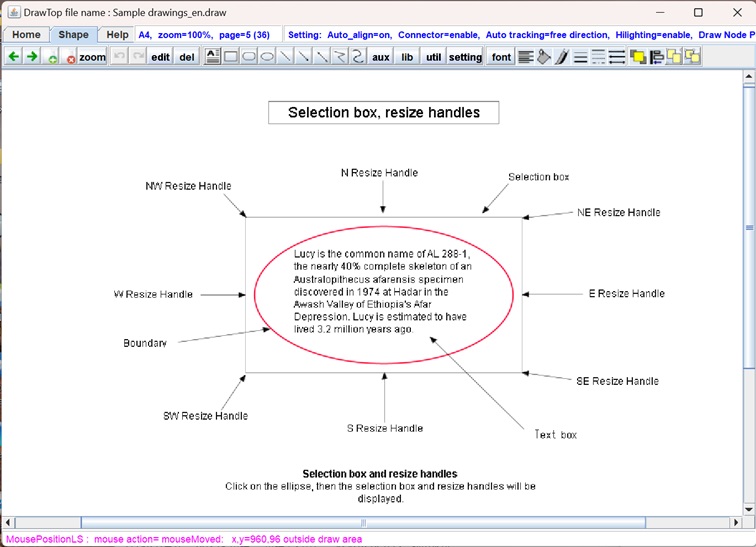
The "Guidance panel" is always displayed above the tool bar.
The left side of the panel shows the paper size, zoom factor and the current
page, and the right side of the panel shows the command guidance.

|
|
Mouse position information panel
|
The "Mouse position information panel" is always displayed at
the bottom of the window and it shows the mouse position in real time.
For example, you move the mouse on a shape boundary, then the following
message will be displayed.

|
|
 Home
Home