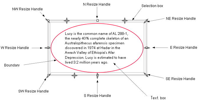
1. Overview
1.1 The cursor marks
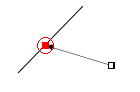
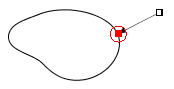
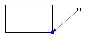
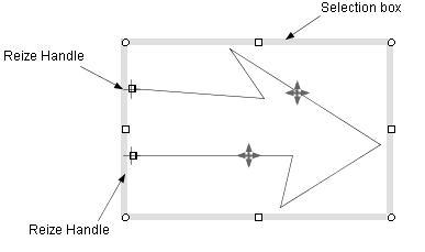
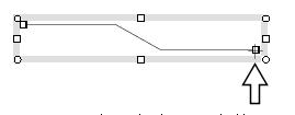
Figure 1.1 shows the cursor marks. When the mouse pointer is located on
a resize handle or a selection box, then the corresponding cursor mark
is displayed. The point to notice here is that the crosshair cursor is
displayed on the endpoints of a line or polyline (Figure_(b), (c)). The
endpoint of the line or polyline can be moved by dragging it with the crosshair
cursor (Figure 1.2(a), Figure 1.2(b)).
Figure_(a) |
Cursor marks:
 |
Figure_(b) |
Figure_(c) |
| Figure 1.1. Selection box, resize handles, and cursor marks. |
1.2 Moving/resizing shapes
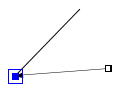
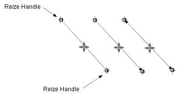
⋅ A straight line
A selection box is not displayed for a selected straight line
(Figure 1.2(a)). To move the line in parallel, drag a point on the line with the move cursor
( ). To resize the line or move the endpoint, drag the end point with the crosshair cursor
( ). To resize the line or move the endpoint, drag the end point with the crosshair cursor
( ,
Figure 1.2(a)). ,
Figure 1.2(a)).
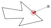
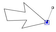
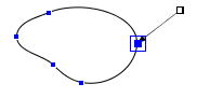
⋅ A polyline
To move a polyline, drag the selection box or a point on the polyline (Figure 1.2(b)). In addition, to move a endpoint of a polyline, move the endpoint
with the crosshair cursor (Figure 1.2(b)).
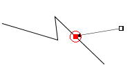
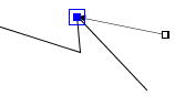
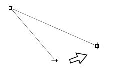
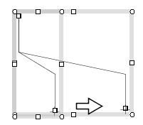
The Figure 1.2(c) shows various cases of moving the end point of a polyline.
The point to notice here is that if a line segment of the polyline
is horizontal or vertical, then it will stay horizontal
or vertical after the endpoint is moved (Figure 1.2(c)).
This feature is important for a connector, because a connector is normally
composed by horizontal and vertical lines.
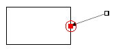
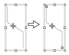
⋅ A closed shape
To move a closed, drag the selection box or a point on the boundary of a closed shape.
To resize a close shape, darg the resize handle (Figure 1.2(d))
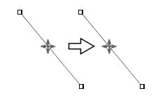
(a) Move in parallel with the move cursor |
(b) Move the endpoint with the crosshair cursor |
Figure 1.2(a) Moving a straight line.
Move in parallel with the move cursor |
Move the endpoint with the crosshair cursor |
Figure 1.2(b) Moving a polyline
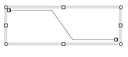
An original polyline |
Moves the end point rightward
with the crosshair cursor |
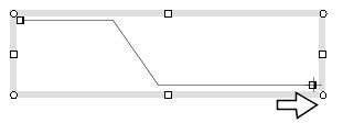
Moves the end point leftward
with the crosshair cursor |
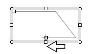
Moves the end point upward
with the crosshair cursor |
Figure 1.2(c) Moving the endpoint of a polyline to various directions.
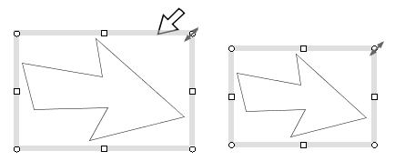
Resize the polyline by dragging the NE resize habdle. |
Resize the ellipse by dragging the N resize habdle. |
Figure 1.2(d) Resizing a closed shape by dragging the resize handle.
1.3 The operation with holding down the Shift, Ctrl or Alt key
| Operation |
Description |
| Moving a shape |
Drag a selection box with holding down the Shift or Ctrl key, then
a shape will be moved horizontally or vertically.
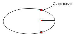
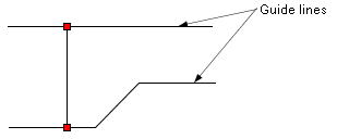
Drag a connector (line or polyline) with holding down the Ctrl/Shift key
and if the connector is connected to guide lines/curves at the endpoints,
then the endpoints of the connector will be moved along the guide lines/curves
(Figure 1.3). This function is used to move lines in a table.
|
| Moving a endpoint of a line or polyline |
Drag a endpoint with holding down the Shift or Ctrl key, then the endpoint
will be moved horizontally or vertically. |
| Resizing a shape |
Drag the NW, SW, SE or NE resize handle with holding
down the Shift or Ctrl key, and then a shape will be resized with keeping
its wide to height ratio.
Drag the NW, SW, SE or NE resize handle with holding
down the Alt key, then a shape will be resized to fit a square rectangle.
|
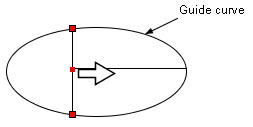
Moves the vertical line to the right
with holding down the Ctrl/Shift key. |
The connections (red marks)
can be preserved. |
 |
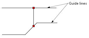 |
Figure 1.3 The effect of the Ctrl/Shfit key
1.4 Auto align
The auto_align function automatically executes the same operation
as the "align objects" command while a shape is moved or
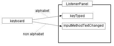
resized. For example, Figure 1.4(a) shows the diagram whose components are
not aligned.
 =>
User's guide align objects =>
User's guide align objects
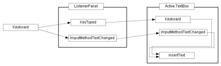
Figure 1.4(a) Sample drawing: block diagram.
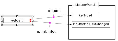
First we move the "Keyboard" box upward. If the "Keyboard"
box is aligned with a neighboring object within a given error margin, red
dashed lines are displayed as Figure 1.4(b). In Figure 1.4(b), the "Keyboard"
box and the "Keytyped" box have the same size, therefore the
three conditions such as align_top, align_middle and align_bottom
are established at the same time and the three red dashed lines are displayed.
If you release the mouse button at this moment, the "Keyboard"
box will be aligned with the "Keytyped" box accurately.
To confirm the align of the two boxes, press the mouse button on the selection
box of the "Keyboard" box, then the three red dashed lines
will be displayed again.
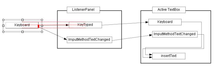
Figure 1.4(b) Move the "Keyboard" box upward
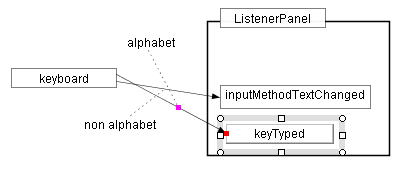
Next, moves the "Keytyped" box slightly to the left, then it
will aligned vertically with the "ListenerPanel" box and horizontally
with the "Keyboard" box and the red dashed lines will be displayed
horizontally and vertically as Figure 1.4(c).
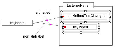
Release the mouse button, then "Keytyped" box will be aligned
with the "ListenerPanel" box and "Keyboard" box simultaneously.
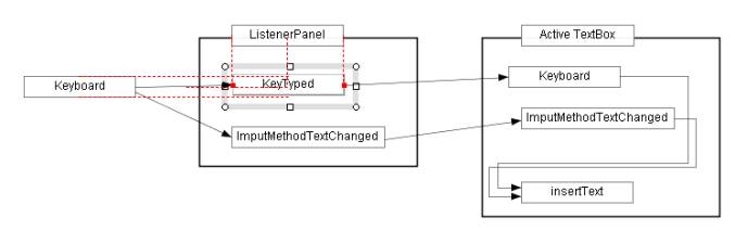
Figure 1.4(c) Move the "Keytyped" box slightly to the left
Repeat the operations, then finally we get Figure 1.4(d).
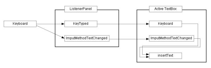
Figure 1.4(d) The completion diagram.
2. Class MoveResizeShapeLS
return=>page top
2.1 Control flow
(1) Moving/Resizing a shape
(2) Connecting a connector
|
Step
|
Description |
| Step1 Displaying a connection point |
Drag the endpoint of a selected line/polyline and move the endpoint to
a target shape, then the red or blue mark will be displayed on the boundary
of the target shape. Here the mark is showing a expected connection point.
To do this processing, the mouseDragged method of this class calls the ConnectionLS.drawMouseHitPT method which displays the connection point if the endpoint is close enough
to the target shape.
=> User's guide Connector, Figure 2.1, 2.2 |
Step2 connecting a connector to a target
|
If the ConnectionLS.drawMouseHitPT method returns a connection point, the mouseDragged method moves the connector's endpoint to the connection point by the ShapeElement.moveEndPoint method. The connection point is calculated very acculately, so the connector's
endpoint lies on the shape boundary within round-off error. |
:
More detailed description =>Connector, ConnectionLS
Figure 2.1 Connecting a line(connector) to a shape boundary.
Figure 2.2 Connecting the line(connector) to a corner (junction/terminal) point.
(3) Maintaining the connection with a target shape
When the target shape is moved or resized, the connectors connecting to the target shape are transformed
and maintains the connections with the target shape. Even if the target
shape belongs to a group, the connection must be maintained.
=>
User's guide Connector
|
Step
|
Description |
| Step1 Initial set |
The start method of this class calls the
setTargets method of the
ConnectionUtil
ich creates the list of the target shapes to be move or resized and
the connectors which connect to the target shapes. |
| Step2 Resizing the connector |
While the target shapes is moved/resized by dragging, the
mouseDragged method of this class calls the
resizeConnectors method of the
ConnectionUtil
which moves the endpoints of the connectors and maintains the connections with the target shapes. |
| Step3 Post process |
When the mouse button is released, the mouseReleased method calls the end method of the ConnectionUtil for post processing. |
: More detailed description =>
Connector Maintaining the connections
(a) original |
(b) moves "keyboad" box to the left. |
(c) moves "keyTyped" box downward. |
(d) moves "InputMethodTextChanged"
and "keyTyped" boxes upward. |
Figure 2.3 Maintaining the connection
Color marks represent the connection points between the shapes being moved
and the connectors
(4) Moving a line or polyline along guide lines or curves (Figure 1.3)
This function is achieved by calling the
setTargets method of the
ConnectionUtil (see (3)) for preparation, and calls the
resizeTargetsByGuideLines method of the
ConnectionUtil in the
mouseDragged method of this class.
2.2 MoveResizeShapeLS API
return=>page top
public class MoveResizeShapeLS implements MouseListener, MouseMotionListener
|
Method
|
Description
|
| start |
public void start(MousePositionInfo info, MouseEvent e),/p>
Parameters:
info - MousePositionInfo data when a mouse is pressed on a selected shape to move or resize the
selected shape.
e - The MouseEvent object which is obtained in the
SelectionLS.mousePressed method.
Processing:
This method is called from the
SelectionLS.prepareMoveResizeCommand via the
ExecCommand.exec method.
The ExecCommand.exec method
creates a new MoveResizeShapeLS object and calls this method.
⋅ Registers this object (MoveResizeShapeLS) to the
ListenerPanel as a MouseListener
and MouseMotionListener, and stops the SelectionLS object
by calling the SelectionLS.end method.
⋅ Calls the init method of this class.
⋅ Calls the undoSetupStart method of the
ContainerManager
|
| init |
public void init(MouseEvent e)
Parameters: The same parameter as the start method
Processing:
This method does the initial setting before the mouse is dragged.
⋅ Sets the MousePositionInfo object to the
mousePositionInfo.
The MousePositionInfo is given by the
MousePositionLS.getMousePositionInfoForMoveResize method.
⋅ Sets the mode using the data in the parameter of the mousePositionInfo.
⋅ Sets the selected shapes to the
selectedContainers.
Gets the selected shapes by using the
ContainerManager.getSelectedContainers method
and stores them to the field of the selectedContainers.
If the mode equals MOVE_ENDPT, the operation is allowed only for lines, open polylines
and open curves. This check is performed by the
isSuitableForMoveEndPT method.
⋅ Calls the ConnectionUtil.setTargets method.
The setTargets method creates the list of the target shapes to be move/resized, and the
list of the connectors which connect to the target shapes.
=>Control flow Connecting a connector
Sets the values to the startBox,
newBox, oldBox etc.
⋅ Initial setting to the ShapeElement.
Calls the ShapeElement.mouseStart method.
⋅ Sets auto_align
If the DrawParameters.AUTO_ALIGN is true,
then this method calls the folowing methods.
・Calls the AutoAlign.start method to set
AUTO_ALIGN.
・Call the ConnectionUtil.start method
to carry out the connector related initial setting (
2.1 (2), 2.1 (3)).
|
| end |
public void end()
⋅ Removes this object from the ListenerPanel and calls the
SelectionLS.start method.
⋅ Calls the ConnectionUtil.end method.
⋅ Calls the undoSetupEnd method of the ContainerManager. |
isSuitableFor
MoveEndPT |
public boolean isSuitableForMoveEndPT(ShapeContainer container)
Returns true if the shape specified by the container is suitable for moving its endpoint.
The endpoint of a line, open polyline or open cubic curve can be moved. |
| mousePressed |
public void mousePressed(MouseEvent e)
This method isn't called because the SelectionLS.mousePressed method already received the MouseEvent object.
=>Control flow Moving/Resizing a shape
|
| mouseDragged |
public void mouseDragged(MouseEvent e)
⋅ Checks whether the Shift/Ctrl/Alt key is held down while dragging.
=>The operation with holding down the Shift, Ctrl or Alt key
⋅ Executes moving or resizing the selected shapes according to the mode.
(a) mode=Command.MOVING_MODE
Calls the ShapeElement.move method.
(b) mode=Command.RESIZING_MODE
Calls the ShapeElement.resize method.
(c) mode=Command.MOVING_ENDPT_MODE
Calls the ShapeElement.moveEndPoint method.
・Caslls the AutoAlign.mouseDragged and the
ConnectionUtil.mouseDragged methods
for the processings of Auto_Align and connectors.
|
| mouseReleased |
public void mouseReleased(MouseEvent e)
⋅ If the DrawParameters.AUTO_ALIGN is true, then this method performs the following.
This method calls the AutoAlign.ajustAlignment method to align the selected shape with a neighboring shape exactly within
round-off error and calls the ConnectionUtil.resizeConnectors method.
⋅ Calls the end method of this class for post processing.
・Caslls the AutoAlign.mouseReleased and the
ConnectionUtil.mouseReleased methods
for the processings of Auto_Align and connectors.
|
|
mouseMoved
|
public void mouseMoved(MouseEvent e)
Nothing is done. |
| mouseClicked |
public void mouseClicked(MouseEvent e)
Nothing is done. |
| mouseEntered |
public void mouseEntered(MouseEvent e)
Nothing is done. |
| mouseExited |
public void mouseExited(MouseEvent e)
Nothing is done. |
 :
The move/resize method of the ShapeElement :
The move/resize method of the ShapeElement
Gets the mouse position code from the MousePositionInfo and determines whether the operation is moving or resizing a shape. Then
calls the corresponding method of the ShapeElement to update the shape data.
Moving is a kind of resizing which changes only the shape position, so
for moving the shape, the ShapeElement.resize method is called.
|
Move
|
If the mouse position code equals SELECTION_BOX, SHAPE_BOUNDARY or INSIDE_SHAPE, then the operation is moving a shape.
=> Calls the ShapeElement.resize method (*1) for moving. |
|
Resize
|
If the mouse position code equals NW_RESIZE, NE_RESIZE, SE_RESIZE, SW_RESIZE, N_RESIZE, E_RESIZE, S_RESIZE or W_RESIZE, then the operation is resizing a shape.
=> Calls the ShapeElement.resize method.
If the mouse position code equals END_POINT, then the operation is moving the endpoint of a line, polyline or cubic
curve.
=> Calls the ShapeElement.moveEndPoint method for moving an endpoint. |
(*1) The resize method can be used for moving a shape.
3. Class AutoAlign
return=>page top
public class AutoAlign
3.1 AutoAlign Examples
=>
Auto align Figure 1.4(a) - 1.4(d) on this page,
User's guide
auto align,
auto align example1 - example5,
Example-1
The auto align capability automatically performs the same operation as the
align command
- align_left, align_center, align_right. align_top, align_middle, align_bottom
- in real time , while the selected shape is being moved or resized.
When you move or resize the selected shape and if the selected shape is aligned to other shapes,
then red dashed lines are displayed.
When you release the mouse button while red dashed lines are being displayed,
the selected shape will be aligned with the other shapes very accurately.
3.2 Control flow
3.3 Summary of the processing
|
Step
|
Description
|
|
Step1. Creating scale marks on the x-axis and y-axis
|
The createAlign method of this class creates
scale marks based on the existing unselected shapes.
The six scale marks - x left, x center, x right, y top, y middle,
y bottom - are created from each of the unselected shapes. The first three
are scale marks on the x-axis and the last three are scale marks on the
y-axis. The scale marks are, of course, not equally spaced.
The scale mark is represented by an Align object.
The Align object has an attribute (alignAxis)
of the Align.XALIGN or Align.YALIGN
which shows whether the scale mark belongs to the x-axis or the y-axis.
The Align objects of Align.XALIGN are further classified
by the sub-attribute (alignType)
into Align.LEFT, Align.CENTER
and Align.RIGHT,
and the Align objects of Align.YALIGN are classified in the same way
into Align.TOP, Align.MIDDLE
and Align.BOTTOM.
The scale marks on the x-axis are saved to xAlignList
and those on the y-axis are saved to yAlignList.
The scale marks are arranged in ascending order in each ArrayList.
The xAlignList and the yAlignList act
as a kind of x-ruler and y-ruler.
For example, to know whether the left side of the selected shape - which is being moved or resized -
is aligned to other unselected shape, we search an Align object whose attribute
and sub attribute are Align.XALIGN and Align.LEFT
and whose value matches the left side of the selected shape.
|
|
Step2. Checking alignment
|
If the selected shape happens to aligned with a scale mark - which we call
"hitAlign"
- in the xAlignList or
yAlignList within a given error margin,
the AutoAlign.createHitAlignedCouples method
creates a new Align object from the selected shape -
which we call "targetAlign".
Then the AutoAlign.createHitAlignedCouples
method creates a new object of the AlignedCouple
which represents a couple of the targetAlign
and the hitAlign
and stores the new AlignedCouple object
in the hitAlignedCouples(Vector object).
: The rules of checking alignment
(1) The moving or resizing operation can handle multiple selected shapes,
however the screen looks so crowded if the auto_align function
displays all the alignments for the multiple selected shapes with red dashed lines.
So the auto_align function is limited to handle the single selected
shape on which the mouse button was pressed.
(2) The alignAxis of the targetAlign
should be the same as that of the hitAlign.
|
Step3. Displaying alignments
=>Figure 1.4(b),(c) |
The drawAlign method of this class displays an alignment by a red dashed line between
the shape denoted by the targetAlign
and hitAlign (see Figure 1.4(b)).
If several shapes are already aligned, then the selected shape being moved/resized may be aligned to many shapes at once,
the drawAlign method may display many overlapped red dashed lines.
This display looks so crowded and the overlapped dashed red lines are unnecessary.
To avoid this, the AutoAlign.selectHitAlignedCouple method selects
AlignedCouple objects.
So, for each alignment of the Align.LEFT, Align.CENTER, .... Align.BOTTOM,
the selectHitAlignedCouple method selects
one or two AlignedCouple objects and stores it to
selectedHitAlignedCouples(Vector).
: Displaying red dashed lines for cubic curves etc.
If the two shapes denoted by the targetAlign
and hitAlign are simple shapes like a rectangle or ellipse,
the interval of the red dashed line can be determined easily.
The Figure (e), (f) shows the alignment of two cubic curves.
In this case, the x interval of the red dashed line can't be determined trivially.
To determine the interval the red dashed line,
the AlignCouple.setAlignPoints sets
the top, middle or bottom points of the two shapes - which are
denoted by the targetAlign
and hitAlign -
by using the Align.getAlignedPoints method (point sampling method).
Thus the drawAlign method of this class draws the red dashed line as Figure (e), (f).
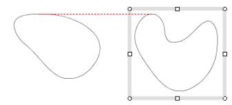
Figure (e) Align top |
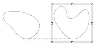
Figure (f) Align bottom |
|
|
Step4.Aligning exactly
|
The two shapes in the targetAlign
and hitAlign are aligned within a given error margin.
The AutoAlign.ajustAlignment method
slightly moves or resizes the shape in the targetAlign
to align it to the hitAlign exactly within round-off error.
: If the cases shown in Figure 1.3, Figure 2.1, 2.2 happen, this step is skipped, because the keeping
connections has high priority.
|
3.4 AutoAlign API
return=>page top
public class AutoAlign
|
Method
|
Description
|
| Constructor |
public AutoAlign(MoveResizeShapeLS moveResizeShapeLS) |
| Constructor |
public AutoAlign(int mode, MousePositionInfo mousePositionInfo, ShapeContainer[]
selectedContainers)
This constructor is called by the init method of the MoveResizeShapeLS.
Parameters:
mode - See the mode field.
mousePositionInfo - See the mousePositionInfo field.
selectedContainers - See the selectedContainers field. |
| start |
public void start(int mode, MousePositionInfo mousePositionInfo, ShapeContainer[] selectedContainers)
⋅ Initial set for AUTO_ALIGN
:
This method called from the MoveResizeShapeLS.init method
is implemented in order to avoid that the MoveResizeShapeLS.init method is too complicated.
|
| mouseDragged |
public void mouseDragged(MouseEvent e)
⋅ Calles the drawHitAligns method of this class.
:
This method is called from the MoveResizeShapeLS.mouseDragged method.
|
| mouseReleased |
public void mouseReleased(MouseEvent e)
⋅ mode=Command.MOVING_ENDPT_MODE
Checks the ConnectionUtil.connected field.
If it is not true, calls the ajustAlignment method of this class.
⋅ mode=Command.MOVING_MODE/RESIZING_MODE
Checks the ConnectionUtil.guided field.
If it is not true, calls the ajustAlignment method.
: This method is called from the
MoveResizeShapeLS.mouseReleased method.
|
| createAlign |
private void createAlign()
=>Summary Step1
This method is called by the constructor.
It creates the six Align objects
- Align.LEFT, Align.CENTER,
Align.RIGHT, Align.TOP,
Align.MIDDLE and Align.BOTTOM - for each unselected shape.
The six Align objects are added
to the xAlignList or yAlignList. |
| putAlign |
private void putAlign(int alignAxis, int alignType, double value, ShapeContainer
shapeContainer)
Parameters:
alignAxis - Align.XALIGN or Align.YALIGN
alignType - Align.LEFT, Align.CENTER, Align.RIGHT, Align.TOP, Align.MIDDLE or Align.BOTTOM
value - The position of an alignment. If alignAxis equals Align.XALIGN, then sets x value, if alignAxis equals Align.YALIGN, then sets y value.
shapeContainer - Represents a shape.
Processing:
This method is called by the createAlign method.
It creates an new Align object whose attributes are specified by the parameters,
and adds the new Align object to the xAlignList
or yAlignList.
The Align objects in the xAlignList
or yAlignList are arranged in ascending order. |
| drawHitAligns |
public void drawHitAligns()
=>Summary Step3
Processing:
This method is called by the mouseDragged and mouseReleased of the MoveResizeShapeLS.
If the shape being moved or resized is aligned to a neighboring shape within
a given error margin, then this method displays a red dashed line. The
createHitAlignedCouples method checks the alignment and calls the drawAlign method of this class to display the red dashed line. |
| createHitAlignedCouples |
private void createHitAlignedCouples(ShapeContainer targetContainer, int
endPTindex)
=>Summary Step2
Parameters:
targetContainer - The shape to be moved or resized on which the mouse button was pressed.
endPTindex - This parameter is effective if the mode equals Command.MOVE_ENDPT
endPTindex=0: The startpoint of the line/polyline/cubic curve is moved.
endPTindex=1: The endpoint of the line/polyline/cubic curve is moved.
endPTindex=-1: Otherwise.
Processing:
This method finds an Align object (stored in the xAlignList
or yAlignList) which the targetContainer is aligned to.
If the Align object (hitAlign) is found,
then this methods creates a new Align object (targetAlign)
from the targetContainer and creates a new AlignedCouple object
using the targetAlign
and the hitAlign.
Finally this method adds the new AlignedCouple object to the
hitAlignedCouples.
|
| selectMovingEndPT |
private int selectMovingEndPT()
This method called by the constructor of this class.
It determines which endpoint of the shape is dragged with the mouse referring
the mousePositionInfo.
If the start point or end point of the shape is being moved, then returns 0 or 1 respectively.
|
| selectHitAlignedCouple |
private AlignedCouple selectHitAlignedCouple(int alignType, int dir)
=>Summary Step3
Parameters:
alignType - The same as Align.alignType.
dir - 0/1
if the dir=0, then returns the AlignedCouple object
whose hitAlignPoint is located around the left side or upper side
of the targetAlignPoint on the screen.
If the dir=1, then returns the AlignedCouple object
whose hitAlignPoint is located at the right side or lower side
of the targetAlignPoint.
Returns: Returns the AlignedCouple object
Processing:
This method is called by the AutoAlign.drawHitAligns method.
This method selects AlignedCouple objects whose targetAlign
and hitAlign have the same alignType
and it equals the alignType parameter.
If the multiple AlignedCouple objects are found, this method selects one AlignedCouple object
whose returned distance by the getAlignOrthogonalDistance
method is minimum.
If the AlignedCouple isn't found, this method returns null.
|
| drawAlign |
private void drawAlign(AlignedCouple couple)
Parameters:
couple - The AlignedCouple object to be displayed with red dashed lines.
Processing:
This method is called by the drawHitAligns method
and displays red dashed lines which shows that the two shapes in the AlignedCouple
are aligned within a given error margin.
The red dashed lines are drawn by the DrawShapeUtil.drawMarkOnDrawPane method.
: Figure 3.1, Figure 3.2, Figure 3.3
|
| ajustAlignment |
public void ajustAlignment(int ctrl)
Parameters:
ctrl - When the mouse is dragged with holding down the Shift/Ctrl/Alt key, then
the ctrl value is 1/2/3 respectively.
The ctrl is passed to ShapeElement.move method.
Processing:
Case 1. this.mode=Command.MOVING_MODE
Step 1. Selects the bestAlignedCouple for each XALIGN and YALIGN.
bestCoupleX=this.getBestAlignedCouple(Align.XALIGN);
bestCoupleY=this.getBestAlignedCouple(Align.YALIGN);
Step 2. Gets the align errors(errorX and errorY) for each XALIGN and YALIGN.
errorX=bestCoupleX.getAlignedError();
errorY=bestCoupleY.getAlignedError();
Step 3. Moves the this.selectedContainers along the vector of (errorX, errorY).
this.selectedContainers[i].getElement().move(ctrl, newP, true);
0≦i<this.selectedContainers.length,
The newP(Point2D.double) is the point created by moving the current mouse position along the vector (errorX, errorY).
:
As the result of above prosessing, the shapeContainer
in the targetAlign is aligned
to the shapeContainer
in the hitAlign accurately within round-off error.
Case 2. this.mode=Command.RESIZING_MODE
In the resizing mode, more detailed specification is required.
For example, if resizing is done by moving NW Resize Handle,
then the TOP and LEFT sides of the shape are needed to be moved,
so the bestAlignedCouple can be selected in the following manner.
Step 1. Selects the bestAlignedCouple for each XALIGN and YALIGN.
bestCoupleX = this.getBestAlignedCouple(Align.XALIGN, Align.LEFT);
bestCoupleY = this.getBestAlignedCouple(Align.YALIGN, Align.TOP);
Step 2. Do the same processing as the Case 1. Step 2
Step 3. Resizes this.selectedContainers
by moving the NW Resize Handle along the vector of (errorX, errorY)
this.selectedContainers[i].getElement().mouseStart(ctrl, P0);
this.selectedContainers[i].getElement().resize(ctrl, P1, mousePosition, true);
Case 3. this.mode=Command.MOVING_ENDPT_MODE
The Align.ENDPT is specified to the second parameter of
the getBestAlignedCouple.
Step 1. Selects the bestAlignedCouple for each XALIGN and YALIGN.
bestCoupleX = this.getBestAlignedCouple(Align.XALIGN, Align.ENDPT);
bestCoupleY = this.getBestAlignedCouple( Align.YALIGN, Align.ENDPT);
Step 2. Do the same processing as the Case 1. Step2
Step 3. Moves the end point of the this.selectedContainers
by the vector of (errorX, errorY).
Here, the end point is specified by the ptIndex given from the selectMovingEndPT.
this.selectedContainers[0].getElement().moveEndPoint(ctrl, ptIndex, newPoint);
:
The connections with connectors are assured in the above processings,
because this method is called from the MoveResizeShapeLS.mouseReleased method.
=> Figure 3.4
|
| getBestAlignedCouple |
private AlignedCouple getBestAlignedCouple(int alignAxis)
Parameters:
alignAxis - XALIGN or YALIGN.
Returns:
AlignedCouple - The best AlignedCouple object
for the ajustAlignment method.
Processing:
This method selects an AlignedCouple object
from the selectedHitAlignedCouples (Vector object)
by specifying the alignAxis attribute and returns the AlignedCouple object.
If the multiple AlignedCouple objects are found, select one by the following manner.
Case 1. Overlapping between the boundingBox of the shape
in the targetAlign and that in hitAlign.
Selects the AlignedCouple object whose overlapping interval is maximum.
Here, the overlapping interval is given by the AlignedCouple.checkIntersection method.
Case 2. No overlapping.
Selects the AlignedCouple object whose align error along alignAxis is minimum
Here, the align error is given by the AlignedCouple.getAlignedError method.
|
| getBestAlignedCouple |
private AlignedCouple getBestAlignedCouple(int alignAxis, int targetAlignType)
More detailed specification can be possible by adding the parameter: targetAlignType.
Parameters:
alignAxis - XALIGN or YALIGN.
targetAlignType - Either from LEFT to ENDP.
Returns:
AlignedCouple - The best AlignedCouple object
for the ajustAlignment method.
Processing:
This method selects an AlignedCouple object
from the selectedHitAlignedCouples (Vector object)
by specifying the alignAxis attribute and returns the AlignedCouple object.
The targetAlignType is used to compare to the alignType
of the couple.targetAlign.
If the multiple AlignedCouple objects are found, select one by the following manner.
Case 1. Overlapping between the boundingBox of the shape
in the targetAlign and that in hitAlign.
Selects the AlignedCouple object whose overlapping interval is maximum.
Here, the overlapping interval is given by the AlignedCouple.checkIntersection method.
Case 2. No overlapping.
Selects the AlignedCouple object whose align error along alignAxis is minimum
Here, the align error is given by the AlignedCouple.getAlignedError method.
|
2.3 AutoAlign support classes
return=>page top
2.3.1 Class Align
An Align object represents the left side position, center position, right
side position, top side position, middle position or bottom side position
of a shape. If the shape is a line, an open polyline or an open cubic curve,
then an Align object also represents the endpoint of the shape.
| Field |
Description |
| alignAxis |
int alignAxis
XALIGN or YALIGN is set to this field. |
| alignType |
int alignType
LEFT, CENTER, RIGHT, TOP, MIDDLE, BOTTOM or ENDPT is set to this field. |
| value |
double value
Alignment position. If alignAxis equals XALIGN, then x value is set to this field.
If alignAxis equals YALIGN, then y value is set to this field. |
| shapeContainer |
ShapeContainer shapeContainer
The shape from which this Align object is originated (=>ShapeContainer). |
| endPTindex |
int endPTindex
If the alignType equals ENDPT and a endpoint of the shape is moved, then this field is
effective.
endPTindex=0: The startpoint of the shape is moved.
endPTindex=1: The endpoint of the shape is moved.
endPTindex=-1: ineffective |
| boundingBox |
Rectangle2D boundingBox
The rectangle which encloses the shape denoted by the shapeContainer.
This field is set by the setBoundingBox method.
If alignType equals ENDPT,
the boundingBox is the rectangle which encloses the startpoint or the endpoint of the shape according to endPTindex,
and its width and height is zero.
|
| alignedPoints |
Point2D[] alignedPoints
this field is set by the setAlignedPoints method.
|
| XALIGN |
static final int XALIGN=10
The constant for the alignAxis. |
| YALIGN |
static final int YALIGN=11
The constant for the alignAxis. |
| LEFT |
static final int LEFT=0
The constant for the alignType. |
| CENTER |
static final int CENTER=1
The constant for the alignType. |
| RIGHT |
static final int RIGHT=2
The constant for the alignType. |
| TOP |
static final int TOP=3
The constant for the alignType. |
| MIDDLE |
static final int MIDDLE=4
The constant for the alignType. |
| BOTTOM |
static final int BOTTOM=5
The constant for the alignType. |
| ENDPT |
static final int ENDPT=6
The constant for the alignType. |
| alignString |
String[] alignString
String[] representing XALIGN, YALIGN, LEFT, CENTER, RIGHT, TOP, MIDDLE, BOTTOM and ENDPT. |
|
Method
|
Description
|
| Constructor |
Align(int alignAxis, int alignType, double value, ShapeContainer shapeContainer)
Sets the parameters to the corresponding fields.
Calls the setBoundingBox and setAlignedPoints methods to set the values to the fields of the boundingBox and alignedPoints. |
| Constructor |
Align(int alignAxis, int alignType, double value, ShapeContainer shapeContainer, int endPTindex)
Sets the parameters to the corresponding fields.
This constructor is used if the shape denoted by the shapeContainer is a line, an open polyline or an open cubic curve.
Calls the setBoundingBox and setAlignedPoints methods to set the values to the fields of the boundingBox and alignedPoints. |
|
setBoundingBox
|
private void setBoundingBox()
Sets the bounding box which encloses the shape denoted by the shapeContainer
to the field variable this.boundingBox.
If the alignType equals ENDPT, then sets the bounding box that encloses the startpoint or the endpoint
of the shape and its width and height are zero.
|
|
setAlignedPoints
|
public Point2D[] getAlignedPoints()
=>Summary Step3 Figure (e), (f)
Returns the points whose x-value or y-value matches the value within a given margin.
If the shape denoted by the shapeContainer is a simple shape, it's easy to obtain the point like top side point,
center point, bottom side point, left side point, middle point or right side point.
If the shape isn't a simple shape, for example a cubic curve, then this
method obtains the points by point sampling method on the boundary of the shape.
|
| getAlignAxis |
int getAlignType()
Returns the alignAxis field.
|
| getAlignType |
int getAlignType()
Returns the alignType field.
|
| getValue |
double getValue()
Returns the value field.
|
| getShapeContainer |
ShapeContainer getShapeContainer()
Returns the shapeContainer field. |
| getEndPTindex |
int getEndPTindex()
Returns the endPTindex field. |
| getBoundingBox |
Rectangle2D getBoundingBox()
Returns the boundingBox field.
|
| getAlignedPoints |
public Point2D[] getAlignedPoints()
Returns the alignedPoints field.
|
| update |
public void update()
Updates this object when this.shapeContainer is updated.
|
| toString |
public String toString()
Returns the string representing this object.
|
2.3.2 Class AlignedCouple
return=>page top
|
Field
|
Description
|
| targetAlign |
protected Align targetAlign
The Align object that is created from the target shape to be moved or resized. |
| hitAlign |
protected Align hitAlign
The Align object which is stored in xAlignList or yAlignList and it is
aligned to the target shape. |
| targetAlignPoint |
protected Point2D targetAlignPoint
The point on the boundary of the shape stored in the targetAlign object.
This point is the start point of a red dashed line that shows the alignment and is set by the
setAlignPointsmetod.
|
| hitAlignPoint |
protected Point2D hitAlignPoint
The point on the boundary of the shape stored in the hitAlign object.
This point is the end point of a red dashed line which shows the alignment and is set by the
setAlignPoints method.
|
Copyright (c) 2009-2013
All other trademarks are property of their respective owners.
|
|
 Home
Home